DM183026-2 Microchip Technology, DM183026-2 Datasheet - Page 16
DM183026-2
Manufacturer Part Number
DM183026-2
Description
KIT EVAL MTOUCH CAPACTIVIE
Manufacturer
Microchip Technology
Series
mTouch™r
Datasheet
1.DM183026-2.pdf
(54 pages)
Specifications of DM183026-2
Sensor Type
Touch, Capacitive
Sensing Range
8 & 12 Buttons/Keys, 2 Sliders
Interface
I²C
Voltage - Supply
5V, USB
Embedded
Yes
Utilized Ic / Part
PIC16F, PIC18F, PIC24F, PIC32MX
Interface Type
USB, I2C, UART
Operating Voltage
5 V
Data Bus Width
32 bit
Silicon Manufacturer
Microchip
Kit Application Type
Sensing - Touch / Proximity
Application Sub Type
Capacitive Touch
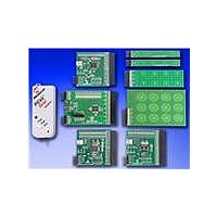
Kit Contents
8x Brds, Serial Anaylizer, USB Cable
For Use With/related Products
PIC16F, PIC24F, PIC18F, PIC32
Lead Free Status / RoHS Status
Lead free / RoHS Compliant
Sensitivity
-
Lead Free Status / Rohs Status
Lead free / RoHS Compliant
Available stocks
Company
Part Number
Manufacturer
Quantity
Price
Company:

Part Number:
DM183026-2
Manufacturer:
Microchip Technology
Quantity:
135
Company:
Part Number:
DM183026-2
Manufacturer:
MICROCHIP
Quantity:
12 000


mTouch™ Advanced Capacitive Evaluation Kits User’s Guide
1.3
DS41385C-page 16
INITIAL BOARD SETUP
With its pre-installed demonstration application, the evaluation board is designed to be
used straight out of the box. Except for a single connection to a computer, no additional
hardware or configuration is necessary.
1.3.1
Before connecting the evaluation board to any computer for the first time, it is important
to install the PC software found on the accompanying CD first. This ensures that the
proper USB drivers for communicating with the evaluation board are installed and ready
to recognize the board.
To install the software and driver, insert the evaluation kit CD into the CD-ROM drive.
The installation process starts automatically. The process pauses for user responses
to accept the Microchip software licenses, and to confirm the installation directories;
you must accept the license to use the software.
1.3.2
Prior to connection, place the evaluation board on a flat surface near the computer.
Check to make sure that there are no objects underneath the board. Once the
evaluation kit software is installed, connect the provided USB cable (A to mini-B) to
any available USB port on the PC or powered hub, and then to the board at the
mini-B receptacle. The PC USB connection provides power to the board.
The PIC24F and PIC18F CTMU and PIC32MX Capacitive Voltage Divider (CVD)
evaluation boards use the USB connection to power up the boards and also to
communicate with the mTouch diagnostic tool. The PIC16F Cap Sense Module (CSM)
and PIC24H CVD evaluation boards use the PICkit Serial Analyzer to communicate to
the PC. Connect the USB cable to the PICkit Serial Analyzer, and connect it to the J2
connector on the board and the PC’s USB port. The default code uses the 8-button
board.
When connecting the PIC24F and PIC18F CTMU and PIC32MX CVD boards, a
sequence of pop-up messages should appear in the system tray (lower right of the
desktop), stating that (1) new hardware has been found, (2) drivers are being installed
and (3) the new hardware is ready for use. If you do not see these messages and the
evaluation board does not work, try unplugging and reconnecting the USB cable. If this
does not work, see Chapter 5. “Troubleshooting”.
Installing the Software
Connecting the Hardware
© 2010 Microchip Technology Inc.
Related parts for DM183026-2
Image
Part Number
Description
Manufacturer
Datasheet
Request
R

Part Number:
Description:
Manufacturer:
Microchip Technology Inc.
Datasheet:
Part Number:
Description:
Manufacturer:
Microchip Technology Inc.
Datasheet:
Part Number:
Description:
Manufacturer:
Microchip Technology Inc.
Datasheet:
Part Number:
Description:
Manufacturer:
Microchip Technology Inc.
Datasheet:
Part Number:
Description:
Manufacturer:
Microchip Technology Inc.
Datasheet:
Part Number:
Description:
Manufacturer:
Microchip Technology Inc.
Datasheet:
Part Number:
Description:
Manufacturer:
Microchip Technology Inc.
Datasheet:
Part Number:
Description:
Manufacturer:
Microchip Technology Inc.
Datasheet: