DM183026 Microchip Technology, DM183026 Datasheet - Page 31
DM183026
Manufacturer Part Number
DM183026
Description
KIT EVALUATION PIC16F/PIC24F
Manufacturer
Microchip Technology
Series
mTouch™r
Datasheet
1.DM183026.pdf
(44 pages)
Specifications of DM183026
Sensor Type
Touch, Capacitive
Embedded
Yes, Other
Utilized Ic / Part
PIC16F727, PIC24FJ128GB106
Processor To Be Evaluated
PIC16F, PIC24F
Interface Type
USB
Silicon Manufacturer
Microchip
Kit Application Type
Sensing - Touch / Proximity
Application Sub Type
Capacitive Touch
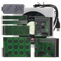
Kit Contents
6x Brds, Analyser, Cable, CD
Lead Free Status / RoHS Status
Lead free / RoHS Compliant
Voltage - Supply
-
Interface
-
Sensitivity
-
Sensing Range
-
Lead Free Status / Rohs Status
Lead free / RoHS Compliant
Available stocks
Company
Part Number
Manufacturer
Quantity
Price
Company:

Part Number:
DM183026
Manufacturer:
Microchip Technology
Quantity:
135
Company:
Part Number:
DM183026-2
Manufacturer:
Microchip Technology
Quantity:
135
Company:
Part Number:
DM183026-2
Manufacturer:
MICROCHIP
Quantity:
12 000


FIGURE 4-4:
4.3
© 2009 Microchip Technology Inc.
INTERFACING THE PLUG-IN BOARDS TO THE CAP TOUCH EVALUATION
BOARDS
CAP TOUCH – CSM EVALUATION BOARD COMPONENT LAYOUT (TOP SIDE)
To interface the plug-in boards to the mTouch Capacitive Evaluation Kit Boards:
1. Connect the evaluation board to the MPLAB
2. Connect the USB receptacle from the workstation to connector J5 of the
3. Connect any of the 4 plug-in boards to the evaluation board through the J4
4. After the hardware connections are done, open the working project in the MPLAB
5. Download the Hex file onto the evaluation board using the MPLAB ICD 2
6. Check the working of the respective plug-in boards and view their output through
- 2-Channel Slider Plug-in Board: The 2-Channel Slider Plug-in board
- 4-Channel Slider Plug-in Board: The 4-Channel Slider Plug-in board
the ICSP™ connector, J1.
evaluation board. This is also used to power-up the evaluation board. For the
CTMU board, it is also used to interface to the PC.
connector (48-pin).
IDE and make the required changes for the corresponding plug-in board, which
is explained in the Readme.txt file. However, the default values of the channel
settings of the corresponding header files are mentioned in
Section 2.2 “Individual Touch Sense Demonstrations”. The default settings
of the configured channels are also explained in the Readme.txt file.
interface.
the 16 LEDs on the evaluation board.
comprises two triangular shaped touch-sensitive pads and a 10-pin connec-
tor (5-pin x 2). The 2-Channel Slider Plug-in board can be connected to any
two adjacent channels from the 16 channels provided by the J4 connector
in the evaluation boards.
comprises 4 touch-sensitive pads and it has a 10-pin connector (5-pin x 2).
The 4-Channel Slider Plug-in board can be connected to any 4 channels
from the 16 channels that are provided by the J4 connector in the evaluation
boards.
Evaluation Board Hardware
®
ICD programmer interface through
DS41385A-page 27
Related parts for DM183026
Image
Part Number
Description
Manufacturer
Datasheet
Request
R

Part Number:
Description:
Manufacturer:
Microchip Technology Inc.
Datasheet:
Part Number:
Description:
Manufacturer:
Microchip Technology Inc.
Datasheet:
Part Number:
Description:
Manufacturer:
Microchip Technology Inc.
Datasheet:
Part Number:
Description:
Manufacturer:
Microchip Technology Inc.
Datasheet:
Part Number:
Description:
Manufacturer:
Microchip Technology Inc.
Datasheet:
Part Number:
Description:
Manufacturer:
Microchip Technology Inc.
Datasheet:
Part Number:
Description:
Manufacturer:
Microchip Technology Inc.
Datasheet:
Part Number:
Description:
Manufacturer:
Microchip Technology Inc.
Datasheet: