DM183026 Microchip Technology, DM183026 Datasheet - Page 11
DM183026
Manufacturer Part Number
DM183026
Description
KIT EVALUATION PIC16F/PIC24F
Manufacturer
Microchip Technology
Series
mTouch™r
Datasheet
1.DM183026.pdf
(44 pages)
Specifications of DM183026
Sensor Type
Touch, Capacitive
Embedded
Yes, Other
Utilized Ic / Part
PIC16F727, PIC24FJ128GB106
Processor To Be Evaluated
PIC16F, PIC24F
Interface Type
USB
Silicon Manufacturer
Microchip
Kit Application Type
Sensing - Touch / Proximity
Application Sub Type
Capacitive Touch
Kit Contents
6x Brds, Analyser, Cable, CD
Lead Free Status / RoHS Status
Lead free / RoHS Compliant
Voltage - Supply
-
Interface
-
Sensitivity
-
Sensing Range
-
Lead Free Status / Rohs Status
Lead free / RoHS Compliant
Available stocks
Company
Part Number
Manufacturer
Quantity
Price
Company:

Part Number:
DM183026
Manufacturer:
Microchip Technology
Quantity:
135
Company:
Part Number:
DM183026-2
Manufacturer:
Microchip Technology
Quantity:
135
Company:
Part Number:
DM183026-2
Manufacturer:
MICROCHIP
Quantity:
12 000


1.1
© 2009 Microchip Technology Inc.
OVERVIEW
Chapter 1. Introduction to the Evaluation Board
Thank you for purchasing Microchip Technology’s mTouch™ Capacitive Evaluation Kit.
These evaluation boards are intended to introduce and demonstrate the possibilities for
capacitive touch sense applications on the PIC16F and PIC24F microcontroller
platforms.
This chapter introduces the evaluation kit and provides an overview of its features.
Topics covered include:
• Overview
• Operational Requirements
• Initial Board Setup
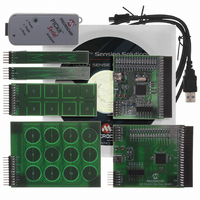
The mTouch Capacitive Evaluation Kit provides a simple platform for developing a
variety of capacitive touch sense applications. Two motherboards are included in the
kit, which connect to the 4 sensor boards, as shown in Figure 1-1 below.
This Capacitive Evaluation Kit is intended to be used to develop sensors and software
using Microchip’s mTouch technologies. It is used by first connecting a sensor board,
and then supplying power to the board via USB, Pickit™ 2, or Pickit Serial Analyzer.
The connector on the right side, with numbers 0 to 15, is the connector for sensing
channels. The number, from 0 to 15, represents the microcontroller’s sensing channel.
The vertical 2-row header is for debugging, to give easy access to some of the
microcontroller pins. Debugging may also be done by Microchip Programmers, or by
I
When using the evaluation kit out of the box, the LEDs default function is to illuminate
on a key press. All functionalities may be reprogrammed by using a Microchip
programmer, and reprogramming the firmware in the device. The firmware supplied
with the evaluation kit has been written to use the four sensor boards supplied.
The USB connection supplies power to the board; no additional external power supply
is needed. For independent operation, the evaluation board may be disconnected from
the PC and powered at test points for independent functionality. For the PIC24F board,
the USB also provides communications. The PIC16F board uses the PICkit Serial
Analyzer to communicate via I
the evaluation kit allows users to monitor the performance of the touch sensors and
calibrate their response. A separate, 6-wire programming interface allows users to
replace the preprogrammed demo firmware with their own applications using
Microchip’s MPLAB Integrated Development Environment and In-Circuit Serial
Programming™ (ICSP™). This allows the board to also be used as a test bed for
capacitive touch sense solutions.
2
C™ or USB with the mTouch Diagnostic Tool.
mTouch™ CAPACITIVE EVALUATION
2
C to the PC. The PC side application that accompanies
KIT USER’S GUIDE
DS41385A-page 7
Related parts for DM183026
Image
Part Number
Description
Manufacturer
Datasheet
Request
R

Part Number:
Description:
Manufacturer:
Microchip Technology Inc.
Datasheet:
Part Number:
Description:
Manufacturer:
Microchip Technology Inc.
Datasheet:
Part Number:
Description:
Manufacturer:
Microchip Technology Inc.
Datasheet:
Part Number:
Description:
Manufacturer:
Microchip Technology Inc.
Datasheet:
Part Number:
Description:
Manufacturer:
Microchip Technology Inc.
Datasheet:
Part Number:
Description:
Manufacturer:
Microchip Technology Inc.
Datasheet:
Part Number:
Description:
Manufacturer:
Microchip Technology Inc.
Datasheet:
Part Number:
Description:
Manufacturer:
Microchip Technology Inc.
Datasheet: