MT9V131C12STCD ES Aptina LLC, MT9V131C12STCD ES Datasheet - Page 6
MT9V131C12STCD ES
Manufacturer Part Number
MT9V131C12STCD ES
Description
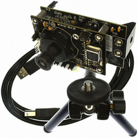
KIT DEMO FOR MT9V131
Manufacturer
Aptina LLC
Series
Micron®DigitalClarity®r
Specifications of MT9V131C12STCD ES
Sensor Type
CMOS Imaging, Color (RGB)
Sensing Range
VGA
Interface
USB
Sensitivity
30 fps
Voltage - Supply
2.55 V ~ 3.05 V
Embedded
No
Utilized Ic / Part
MT9V131
Silicon Manufacturer
Aptina Imaging
Application Sub Type
Image Sensor
Kit Application Type
Sensing - Image / Light
Silicon Core Number
MT9V131
Kit Contents
Board And Literature
Rohs Compliant
Yes
Lead Free Status / RoHS Status
Not applicable / Not applicable
Other names
557-1242


Table 4:
PDF: 09005aef824c99b3/Source: 009005aef824c99bb
MT9V131_LDS_2.fm - Rev. B 3/07 EN
FRAME_VALID
LINE_VALID
ADC_TEST
STANDBY
SCAN_EN
Symbol
VAAPIX
RESET#
PIXCLK
FLASH
D
D
D
D
D
D
D
D
CLKIN
S
S
A
D
SCLK
OE#
V
ADDR
DATA
V
OUT
OUT
OUT
OUT
OUT
OUT
OUT
OUT
NC
GND
GND
DD
AA
7
6
5
4
3
2
1
0
Ball and Pin Description
7, 17, 25, 40, 41, 44,
5, 12, 24, 36, 38, 43,
6, 18, 30, 42
CLCC Pin
26, 28
27, 29
20
21
23
31
33
34
35
39
22
13
14
15
16
45
46
47
32
48
1
2
3
4
8
9
A1, D1, A4, A7,
A6, B2, B4, B6,
C7, D7, G1, G4
B7, C5, E5, F2
iCSP Ball
G5, G6
MT9V131: 1/4-Inch SOC VGA CMOS Digital Image Sensor
C1, D2
F5, G7
G2
D6
G3
A5
A3
A2
F3
F4
F6
E6
E7
C6
E2
E1
E3
F1
B5
C3
B3
B1
C2
F7
Output
Output
Output
Output
Output
Output
Output
Output
Output
Output
Output
Output
Supply
Supply
Supply
Supply
Supply
Input
Input
Input
Input
Input
Input
Input
Input
Type
6
I/O
–
Master clock into sensor. Default is 12 MHz (27 MHz
maximum).
Serial clock.
Serial interface address select: Reg0xB8 when HIGH
(default).
Reg0x90 when LOW.
Tie to VAAPIX (factory use only).
Asynchronous reset of sensor when LOW. All registers
assume factory defaults.
When HIGH, puts the imager in ultra-low power
standby mode.
Output_Enable_Bar pin. When HIGH, tri-state all
outputs except S
Tie to digital ground.
Serial data I/O.
Flash strobe.
Pixel clock out. Pixel data output are valid during
rising edge of this clock. IFP Reg0x08 [9] inverts
polarity.
Frequency = Master clock.
Active HIGH during line of selectable valid pixel data.
Active HIGH during frame of valid pixel data.
ITU_R BT.656/RGB data bit 7 (MSB).
ITU_R BT.656/RGB data bit 6.
ITU_R BT.656/RGB data bit 5.
ITU_R BT.656/RGB data bit 4.
ITU_R BT.656/RGB data bit 3.
ITU_R BT.656/RGB data bit 2.
ITU_R BT.656/RGB data bit 1.
ITU_R BT.656/RGB data bit 0 (LSB).
Digital power (2.8V).
Analog power (2.8V).
Pixel array power (2.8V).
Analog ground.
Digital ground.
No connect.
Micron Technology, Inc., reserves the right to change products or specifications without notice.
DATA
Description
(tie LOW for normal operation).
©2006 Micron Technology, Inc. All rights reserved.
Ball Assignment
Preliminary
Related parts for MT9V131C12STCD ES
Image
Part Number
Description
Manufacturer
Datasheet
Request
R

Part Number:
Description:
Vga 1/4-inch Soc Image Sensor
Manufacturer:
aptina
Datasheet:
Part Number:
Description:
Mt9v131 1/4-inch Soc Vga Cmos Digital Image Sensor
Manufacturer:
aptina
Datasheet:

Part Number:
Description:
SENSOR IMAGE VGA COLOR CMOS PLCC
Manufacturer:
Aptina LLC
Datasheet:

Part Number:
Description:
IC SENSOR IMAGE COLOR 48CLCC
Manufacturer:
Aptina LLC
Datasheet:

Part Number:
Description:
SENSOR IMAGE 1.3MP CMOS 48-CLCC
Manufacturer:
Aptina LLC
Datasheet:

Part Number:
Description:
SENSOR IMAGE 2MP CMOS 48-CLCC
Manufacturer:
Aptina LLC
Datasheet:

Part Number:
Description:
SENSOR IMAGE VGA MONO 52IBGA
Manufacturer:
Aptina LLC
Datasheet:

Part Number:
Description:
SENSOR IMAGE VGA COLOR 48CLCC
Manufacturer:
Aptina LLC
Datasheet:

Part Number:
Description:
SENSOR IMAGE COLOR CMOS 48-PLCC
Manufacturer:
Aptina LLC
Datasheet:

Part Number:
Description:
KIT HEAD BOARD FOR MT9P031
Manufacturer:
Aptina LLC
Datasheet:
Part Number:
Description:
SENSOR IMAGE VGA COLOR CMOS PLCC
Manufacturer:
Aptina LLC
Datasheet:
Part Number:
Description:
IC SENSOR IMAGE COLOR 48CLCC
Manufacturer:
Aptina LLC
Datasheet:
Part Number:
Description:
SENSOR IMAGE 2MP CMOS 48-CLCC
Manufacturer:
Aptina LLC
Datasheet:
