EVB90614 Melexis Inc, EVB90614 Datasheet
EVB90614
Specifications of EVB90614


Related parts for EVB90614


EVB90614 Summary of contents
Page 1
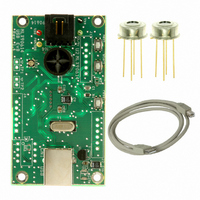
... MLX90614 Single and Dual zone Infra Red thermometer Evaluation Board 390129061401 Rev 004 MLX90614 Evaluation board EVB90614 User Manual Page USER MANUAL User Manual Jan/2008 ...
Page 2
... Demonstration of SMBus and PWM temperature measuring ..................................................................................................... 12 5.6 Quick customization of MLX90614 thermometers...................................................................................................................... 15 5.7 Updating EVB90614 firmware ................................................................................................................................................... 17 5.8 Automatic emissivity correction.................................................................................................................................................. 19 6 Troubleshooting............................................................................................................ 20 7 Disclaimer...................................................................................................................... 21 ♦APPENDIX A – EVB90614 commands set ...................................................................... 21 ♦APPENDIX B – EVB90614 schematics............................................................................ 22 390129061401 Rev 004 MLX90614 Evaluation board Table of Contents ...
Page 3
... CD-ROM drive (for use with the accompanying CD) • Microsoft Windows 98, Second Edition (98SE), Windows 2000 Desktop or Windows XP Note 1: EVB90614 is HID USB device and will require no drivers on PCs that support HID class USB devices (except Microsoft Windows 98, Second Edition (98SE)). Check www ...
Page 4
... Button “next” 4. Button “start” 5. Button “reset” 6. RGB status LED 7. USB "B" Receptacles The EVB90614 board receives its power supply only from the USB cable (Bus-Powered Device). External power supply source is not needed. 390129061401 Rev 004 USER MANUAL MLX90614 Evaluation board ...
Page 5
... USB hub connected to the host system, and to the USB connector on the board. The LED will shine in BLUE. 3. EVB90614 evaluation board is HID compliant device so a special USB device driver is not needed (except when using Window 98 & 98SE). 4. Check the board connection. This can be done from Start/Settings/Control Panel/ System/Hardware/Device Manager (Fig ...
Page 6
The Configurator automatically recognizes the module type, address and voltage supply (Fig. 5.1). The status LED is shinning GREEN. If there is no thermometer module inserted on the EVB or the module is not a MLX90614, the user will be ...
Page 7
... Opens “Configuration uploader” window for quick replication of MLX90614 infrared modules’ configuration. Opens “Advanced” window from which user can upgrade EVB firmware, change measuring unit of the temperature scale and relocate the log file. Opens current EVB90614 User Manual recommended to check www.melexis.com 390129061401 Rev 004 ...
Page 8
Opens “Configuration utility” window used for configuring MLX90614 infrared thermometers. Opens “Measure utility” window for temperature measurements. Dual zone module identification picture. Single zone module identification picture. Cyclop module identification picture. Module type and SMBus slave address identification fields. Show ...
Page 9
From this window the user can configure the MLX90614 module. A short description of every setting field follows bellow. For a detailed description of the settings please refer to the MLX90614 datasheet. These settings are stored in MLX90614 EEPROM and ...
Page 10
Note 7: Bits <3>, <13:11> and <15> of ConfigRegister1 (EPROM address 0x05) can’t be changed from this window because contains a specific information. They can be changed only using the command we (see 5.4 Manual sending commands) Note 8: Do ...
Page 11
Manual sending commands From the main panel push the button Console. ”Console utility” window is opened (Fig.5.12). Type a valid command in the Command field, push Execute (or button ‘Enter’ on the keyboard). The result will be reflected in ...
Page 12
Demonstration of SMBus and PWM temperature measuring From the main panel push the button Measure. The ”Measure utility” window is opened (Fig.5.13). Note 9: If the used module is single zone only two thermometers will be present on the ...
Page 13
Min/Max boxes on this screen. An example is shown on Fig.5.15. In the field “Measure period” the user can make the measuring faster or slower. Max and Min fields permit user to change ...
Page 14
... SMBus Request command and the shown below pictures show how the real Thermo Relay output should keep itself. Fig. 5.17 To use EVB90614 with modules with fixed PWM output (no SMBus access is available) the following option can be used: 1. Click the button Advanced from main panel 4. Click the button PWM-M available in “ ...
Page 15
The window “PWM detached measurement module” is opened (Fig. 5.19). All settings must be entered manually by the user. In Slowdown field user can write value between 0 and 100. Bigger value in this field will make the thermometer readings ...
Page 16
The user has two choices to load an EEPROM configuration in a MLX90614 module: ● Upload ● Quick upload When the Upload button is pushed the software automatically checks the module power supply before writing the EEPROM memory of the ...
Page 17
... EVB MCU. This makes possible for the user to load updates into the EVB using the same software. This can be done by two ways: Updating EVB90614 firmware – method 1 1. Start MLX90614 Configurator 2. Push the button Advanced from the main panel. “Advanced” window is opened (Fig. ...
Page 18
... Wait until a message box appears (Fig. 5.25). Close this window. The EVB90614 board is updated and ready for work incompatible file is loaded warning messages will appear. Follow these messages to load a compatible file. Updating EVB90614 firmware – method 2 1. Close MLX90614 Configurator 2. Press and hold the button start on the board 3 ...
Page 19
Automatic emissivity compensation 5.8 This option allows automatic emissivity compensation in a MLX90614 when an object with emissivity lower than 1 is measured. Most materials have an emissivity close to 1 and a correction is not needed. This routine can ...
Page 20
... If the temperature difference between Ta and Toreal is lower than 5 ° warning appears (Fig. 5.29). 6 Troubleshooting If the USB communication with EVB90614 fails or the MLX90614 Configurator hangs, close the program, push the button reset on the board (the LED must shines BLUE) and launch the program again. ...
Page 21
Disclaimer Devices sold by Melexis are covered by the warranty and patent indemnification provisions appearing in its Term of Sale. Melexis makes no warranty, express, statutory, implied description regarding the information set forth herein or regarding the ...
Page 22
... A – EVB90614 commands set 1. Read MLX90614 RAM address Syntax: rr Operands: 0(0x0) ≤ address ≤31(0x1F) 2. Read MLX90614 EEPROM address Syntax: re Operands: 0(0x0) ≤ address ≤31(0x1F) 3. Write MLX90614 EEPROM address Syntax: we address value Operands: 0(0x0) ≤ address ≤31(0x1F) 0(0x0) ≤ 4. Restart MLX90614 (turn off-turn on module power supply) ...
Page 23
... Note: If user decides to add own firmware using EVB90614 he must use program memory above 0x4000 (see PIC18F4550 datasheet). Also EEPROM memory addresses between 0x40 and 0x43 must be maintained 0x00 or 0xFF otherwise the EVB90614 will not be recognized from the host when bootloader mode. For the latest information about this opportunity check ...