ATAVRTS2080A Atmel, ATAVRTS2080A Datasheet - Page 53
ATAVRTS2080A
Manufacturer Part Number
ATAVRTS2080A
Description
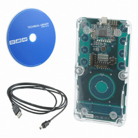
KIT QTOUCH W/SW ATMEGA88
Manufacturer
Atmel
Series
QTouch™r
Specifications of ATAVRTS2080A
Sensor Type
Touch, Capacitive
Sensing Range
1 Rotor, 1 Slider, and 2 Buttons/Keys
Interface
Application Programming Interface (API)
Voltage - Supply
1.8 V ~ 5.5 V
Embedded
Yes, MCU, 8-Bit
Utilized Ic / Part
ATmega88
Tool Type
Development Kit
Cpu Core
AVR 8 / 32
Data Bus Width
8 bit
Core Architecture
AVR
Silicon Manufacturer
Atmel
Silicon Core Number
ATmega88, ATmega88A
Silicon Family Name
AVR
Kit Contents
Board, CD
Development Tool Type
Hardware / Software - Eval/Demo Board
Rohs Compliant
Yes
Lead Free Status / RoHS Status
Lead free / RoHS Compliant
Sensitivity
-
Lead Free Status / Rohs Status
Details


The host application must provide the current time to the library. This information is passed to the
library as an argument to the function qt_measure_sensors()”. This is used for time-based library
operations such as drift compensation.
5.6.10.3 Integrating QMatrix acquisition method libraries in your application
Based on the application design needs, the user needs to select the right library variant and the
configuration to be used along with the variant. This section illustrates the steps required to select
the right QMatrix acquisition method library variant and configuration for your application. QMatrix
acquisition method library Variants are offered for IAR and AVR-GCC tool chains. First step is to
select the compiler tool chain for which the libraries are required. The list of supported compiler
tool chains can be found in section 5.7.2.2
There are specific library variants distributed for each microcontroller. For your design, you would
need the following information to select the correct library variant
Follow the steps listed below to arrive at the right library variant
a. Device to be used for the design
b. The number of touch sensing channels needed by the application – Then identify the
c. Number of X lines to be used in the design
d. Number of Y lines to be used in the design
e. Do you need support for Rotors and/or Sliders in your design
f.
1) Select the device from the list of supported devices listed in 5.7.2.4.1
2) Select the right library variant for the device selected from the selection guide available
3) Define the constants and symbol names required
The 16 bit timer in each device has been used for performing touch measurements
periodically. The datasheet for all the devices have to be checked to ensure that the
correct timer peripheral and its registers are used (file: main.c).
The interrupt vector macro may also change from device to device and this needs to be
verified in the datasheet for the device used.
Check if the timer is configured correctly to support the measurement period needed (e.g.
25msec or 50 msec).
The sample applications for the evaluation kits and supported devices illustrate the
proper initialization sequence and usage of the timer resources (file: main.c). Please use
this as a reference for your application design.
Maximum number of channels required for the design that are supported by the library.
Which compiler platform you intend to use to integrate the libraries – IAR or AVR -GCC
in
C:\ Program Files\Atmel\Atmel_QTouch_Libaries_4.x\Library_Selection_Guide.xls
Each variant supports
a. The ports on which your design permits to have the X lines
b. The X lines can be spread on a maximum of three ports, the more ports used the
a. The port-pins ports on which your design permits to have the Y lines
a. If yes, how many rotors/sliders would be needed?
b. Based on a) above, identify the maximum number of rotors sliders that the library
a. a specific number of channels,
b. Supports a specific configuration of X x Y matrix pins ( eg 4 x 2 for 4 - X pins & 2
c. has support for Rotor / Slider ( either supported or not )
d. support is available for IAR and/or GCC compiler tool chain
e. support for specific number of rotors sliders.
a. The next step is to define certain constants and symbols required in the host
more is the code memory requirement by the library.
supports
- Y pins )
application files where the touch API is going to be used. These values are
derived from the parameters defined in step 2 for your application
53
Related parts for ATAVRTS2080A
Image
Part Number
Description
Manufacturer
Datasheet
Request
R


Part Number:
Description:
DEV KIT FOR AVR/AVR32
Manufacturer:
Atmel
Datasheet:

Part Number:
Description:
INTERVAL AND WIPE/WASH WIPER CONTROL IC WITH DELAY
Manufacturer:
ATMEL Corporation
Datasheet:
Part Number:
Description:
Low-Voltage Voice-Switched IC for Hands-Free Operation
Manufacturer:
ATMEL Corporation
Datasheet:
Part Number:
Description:
MONOLITHIC INTEGRATED FEATUREPHONE CIRCUIT
Manufacturer:
ATMEL Corporation
Datasheet:
Part Number:
Description:
AM-FM Receiver IC U4255BM-M
Manufacturer:
ATMEL Corporation
Datasheet:
Part Number:
Description:
Monolithic Integrated Feature Phone Circuit
Manufacturer:
ATMEL Corporation
Datasheet:
Part Number:
Description:
Multistandard Video-IF and Quasi Parallel Sound Processing
Manufacturer:
ATMEL Corporation
Datasheet:
Part Number:
Description:
High-performance EE PLD
Manufacturer:
ATMEL Corporation
Datasheet:
Part Number:
Description:
8-bit Flash Microcontroller
Manufacturer:
ATMEL Corporation
Datasheet:
Part Number:
Description:
2-Wire Serial EEPROM
Manufacturer:
ATMEL Corporation
Datasheet: