ATAVRTS2080A Atmel, ATAVRTS2080A Datasheet - Page 44
ATAVRTS2080A
Manufacturer Part Number
ATAVRTS2080A
Description
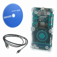
KIT QTOUCH W/SW ATMEGA88
Manufacturer
Atmel
Series
QTouch™r
Specifications of ATAVRTS2080A
Sensor Type
Touch, Capacitive
Sensing Range
1 Rotor, 1 Slider, and 2 Buttons/Keys
Interface
Application Programming Interface (API)
Voltage - Supply
1.8 V ~ 5.5 V
Embedded
Yes, MCU, 8-Bit
Utilized Ic / Part
ATmega88
Tool Type
Development Kit
Cpu Core
AVR 8 / 32
Data Bus Width
8 bit
Core Architecture
AVR
Silicon Manufacturer
Atmel
Silicon Core Number
ATmega88, ATmega88A
Silicon Family Name
AVR
Kit Contents
Board, CD
Development Tool Type
Hardware / Software - Eval/Demo Board
Rohs Compliant
Yes
Lead Free Status / RoHS Status
Lead free / RoHS Compliant
Sensitivity
-
Lead Free Status / Rohs Status
Details


Note: The above constraints are explained with respect to 8bit AVR. The same could be extended
to 32bit AVR and ATSAM for 32 channel libraries where each port has 32 pins.
5.6.7.2
QMatrix acquisition method libraries are available for a set of AVRs The library variants can be
configured to have port and pin assignments for X, Ya, Yb and SMP. Please refer to section 5.8.2
for port-pin configurability.
Some of the key constraints are
44
•
•
•
•
•
•
•
•
•
•
•
If two port pairs are used for the design, all the channels for a sensor have to be
connected on a single port pair. Combining channels from multiple ports is not possible
when designing sensors. e.g. It is not possible to have a rotor with channel numbers (
7,8,9 ) on a 16 channel library variant which uses two port-pairs.
The QMatrix acquisition method libraries internally use TIMER1 for the operation,
TIMER1 will not be available for critical sections of the code where the library is called.
But resources are available to the host application when the normal user’s application is
running.
In case of XMEGA™ devices, the resources are used internal to the library and hence
cannot be used by the host application
The sensor channel number and the relation with X and Y lines strictly follows from the
table provided in the section Table 1.
A rotor /slider sensor can be configured with 3 to 8 channels per rotor or slider depending
on the requirement of the application subject to the total number of channels available in
the library variant selected as listed below.
For example, 16 channel libraries with 4X and 4Y lines supports maximum of 4 channels
per Rotor/Slider. But, a 16 channel with 8X and 2Y lines supports maximum of 8
channels per Rotor/Slider.
If the lines of the Drive and Receive electrode (X lines or the Y lines) share the same
lines with the JTAG, JTAG needs to be disabled. Please check the data sheet to ensure
that there are no conflicts between the X/Y lines and JTAG lines used for the device.
YB line for a particular device cannot be changed and it has to be the configured to be
the ADC port of the selected device.
The AIN0 pin of the device needs to be connected to the GND.
In case of XMEGA devices, the reference pin for input to analog comparator is Pin7 of
PORTA with all the combinations of libraries supported. Hence, this needs to be
connected to GND
Proper grounding should be taken care when the controller board and touch sensing
board are different.
QMatrix acquisition method constraints
o
o
o
Timer/Counter 1 on PORTC (TCC1)
Analog Comparator on PORTA (ACA)
Event System Channel0 (EVSYS_CH0)
Number of
channels
16
16
32
56
64
4
8
X x Y
4 x 1
4 x 2
4 x 4
8 x 2
8 x 4
8 x 7
8 x 8
Maximum Channels per ROTOR_SLIDER
4
4
4
8
8
8
8
8207J-AT42-02/11
Related parts for ATAVRTS2080A
Image
Part Number
Description
Manufacturer
Datasheet
Request
R


Part Number:
Description:
DEV KIT FOR AVR/AVR32
Manufacturer:
Atmel
Datasheet:

Part Number:
Description:
INTERVAL AND WIPE/WASH WIPER CONTROL IC WITH DELAY
Manufacturer:
ATMEL Corporation
Datasheet:
Part Number:
Description:
Low-Voltage Voice-Switched IC for Hands-Free Operation
Manufacturer:
ATMEL Corporation
Datasheet:
Part Number:
Description:
MONOLITHIC INTEGRATED FEATUREPHONE CIRCUIT
Manufacturer:
ATMEL Corporation
Datasheet:
Part Number:
Description:
AM-FM Receiver IC U4255BM-M
Manufacturer:
ATMEL Corporation
Datasheet:
Part Number:
Description:
Monolithic Integrated Feature Phone Circuit
Manufacturer:
ATMEL Corporation
Datasheet:
Part Number:
Description:
Multistandard Video-IF and Quasi Parallel Sound Processing
Manufacturer:
ATMEL Corporation
Datasheet:
Part Number:
Description:
High-performance EE PLD
Manufacturer:
ATMEL Corporation
Datasheet:
Part Number:
Description:
8-bit Flash Microcontroller
Manufacturer:
ATMEL Corporation
Datasheet:
Part Number:
Description:
2-Wire Serial EEPROM
Manufacturer:
ATMEL Corporation
Datasheet: