ATAVRQTOUCHX Atmel, ATAVRQTOUCHX Datasheet - Page 77
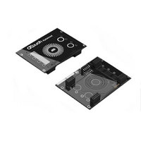
ATAVRQTOUCHX
Manufacturer Part Number
ATAVRQTOUCHX
Description
BOARD EVAL CAPACITIVE TOUCH
Manufacturer
Atmel
Series
QTouch™r
Specifications of ATAVRQTOUCHX
Sensor Type
Touch, Capacitive
Sensing Range
1 Slider, 1 Wheel, 2 Buttons
Interface
USB
Voltage - Supply
5V, USB
Embedded
Yes, MCU, 8-Bit
Utilized Ic / Part
AT90USB1287, ATxmega128A1
Silicon Manufacturer
Atmel
Silicon Family Name
ATxmega
Kit Contents
Board
Svhc
No SVHC (15-Dec-2010)
Core Architecture
AVR
Core Sub-architecture
AVR19
Kit Features
One Slider, One Wheel And 2
Rohs Compliant
Yes
Lead Free Status / RoHS Status
Lead free / RoHS Compliant
Sensitivity
-
Lead Free Status / Rohs Status
Lead free / RoHS Compliant
Available stocks
Company
Part Number
Manufacturer
Quantity
Price
Company:

Part Number:
ATAVRQTOUCHX
Manufacturer:
Atmel
Quantity:
135


5.7.1.5.2.1 Tips on pin assignments for the sensor design using two pairs of SNS / SNSK
This section lists tips on selecting the pin assignments when using a single port pair for the SNS
and SNSK Pins.
Design choice for the sensor
SNSK1-SNS1 & SNSK2-SNS2 pins
are all on different ports, number of
channels = 16
(Use the 16channel library in this
case. Ensure the port definitions for
SNS1,SNSK1,SNS2,SNSK2 are all in
place)
SNSK1-SNS1 are on same port &
SNSK2-SNS2 pins are on same port,
number of channels = 8
(Use the 8channel library in this case.
Ensure the port definitions for
SNS1,SNSK1,SNS2,SNSK2 are all in
place)
SNSK1-SNS1 are on different ports &
SNSK2-SNS2 pins are on same port,
number of channels = 12
(Use the 12channel library in this
case. Ensure the port definitions for
SNS1,SNSK1,SNS2,SNSK2 are all in
place)
SNSK1-SNS1 are on same port &
SNSK2-SNS2 pins are on different
ports, number of channels = 12
(Use the 12channel library in this
case. Ensure the port definitions for
SNS1,SNSK1,SNS2,SNSK2 are all in
place)
ports
Example Port configuration with pin assignments
•
•
•
•
•
•
•
•
•
•
•
•
E. g. SNS1(D), SNSK1(B) & SNS2(C), SNSK2(A)
Recommended configuration: (PD0, PB0), (PD1, PB1),..(PD7,
PB7), (PC0,PA0).. to (PC7, PA7). In this case channel 0 will be
on (PD0, PB0) pins, channel 1 will be on (PD1, PB1) pins,
channel 8 will be on (PC0, PA0), channel 9 will be on (PC1,
PA1) and so on up to channel 15 will be on (PC7, PA7) pins.
However, the user can mount the sensors on pins as selected
as per the rules illustrated in section 5.8.1
should be assigned as given in section 5.6.6.1.1.2
E.g. SNS1(K), SNSK1(K) & SNS2(H), SNSK2(H) on same
ports,
Recommended configuration: In case Pin configurability is not
used, (PK0, PK1), (PK2, PK3),..(PK6, PK7), (PH0,PH1).. to
(PH6, PH7).In this case channel 0 will be on (PK0, PK1) pins,
channel 1 will be on (PK2, PK3) pins, channel 4 will be on
(PH0, PH1), channel 5 will be on (PH2, PH3) and so on up to
channel 7 will be on (PH6, PH7) pins. The even pins of the port
are used as SNS pins and odd pins of the port are used as
SNSK pins.
When pin configurability is used, sensors should be mounted
on the pins as selected as per the rules illustrated in section
5.8.1 and channels should be assigned as given in section
5.6.6.1.1.2
E.g. SNS1(H), SNSK1(F) on different ports & SNS2(E),
SNSK2(E) on same ports.
Recommended configuration : In case Pin configurability is not
used, (PH0, PF0), (PH1, PF1),..(PH7, PF7), (PE0,PE1).. to
(PE6, PE7). In this case channel 0 will be on (PH0, PF0) pins,
channel 1 will be on (PH1, PF1) pins... channel 8 will be on
(PE0,PE1), channel 9 will be on (PE2,PE3) and so on up to
channel 11 will be on (PH6, PH7) pins. The even pins of the
port E are used as SNS pins and odd pins of the port E are
used as SNSK pins.
When pin configurability is used, sensors should be mounted
on the pins as selected as per rules illustrated in section 5.8.1
and channels should be assigned as given in section
5.6.6.1.1.2 and section 5.6.6.1.1.4
E.g. SNS1(G), SNSK1(G) on different ports & SNS2(B),
SNSK2(D) on same ports
Recommended configuration: In case Pin configurability is not
used, (PG0, PG1), (PG2, PG3),..(PG6, PG7), (PB0,PD0)... to
(PB7, PD7). In this case channel 0 will be on (PG0, PG1) pins,
channel 1 will be on (PG2, PG3) pins... channel 3 will be on
(PG6, PG7), channel 4 will be on (PB0,PD0) and so on up to
channel 11 will be on (PB7, PD7) pins. The even pins of the
port G are used as SNS pins and odd pins of the port G are
used as SNSK pins
When pin configurability is used, sensors should be mounted
and channels
77
Related parts for ATAVRQTOUCHX
Image
Part Number
Description
Manufacturer
Datasheet
Request
R


Part Number:
Description:
DEV KIT FOR AVR/AVR32
Manufacturer:
Atmel
Datasheet:

Part Number:
Description:
INTERVAL AND WIPE/WASH WIPER CONTROL IC WITH DELAY
Manufacturer:
ATMEL Corporation
Datasheet:
Part Number:
Description:
Low-Voltage Voice-Switched IC for Hands-Free Operation
Manufacturer:
ATMEL Corporation
Datasheet:
Part Number:
Description:
MONOLITHIC INTEGRATED FEATUREPHONE CIRCUIT
Manufacturer:
ATMEL Corporation
Datasheet:
Part Number:
Description:
AM-FM Receiver IC U4255BM-M
Manufacturer:
ATMEL Corporation
Datasheet:
Part Number:
Description:
Monolithic Integrated Feature Phone Circuit
Manufacturer:
ATMEL Corporation
Datasheet:
Part Number:
Description:
Multistandard Video-IF and Quasi Parallel Sound Processing
Manufacturer:
ATMEL Corporation
Datasheet:
Part Number:
Description:
High-performance EE PLD
Manufacturer:
ATMEL Corporation
Datasheet:
Part Number:
Description:
8-bit Flash Microcontroller
Manufacturer:
ATMEL Corporation
Datasheet:
Part Number:
Description:
2-Wire Serial EEPROM
Manufacturer:
ATMEL Corporation
Datasheet: