MCP6SX2DM-PCTLPD Microchip Technology, MCP6SX2DM-PCTLPD Datasheet - Page 17
MCP6SX2DM-PCTLPD
Manufacturer Part Number
MCP6SX2DM-PCTLPD
Description
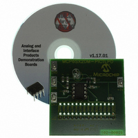
BOARD DAUGHTER PICTAIL MCP6SX2
Manufacturer
Microchip Technology
Series
PICtail™r
Datasheets
1.AC164120.pdf
(36 pages)
2.MCP6SX2DM-PCTLPD.pdf
(28 pages)
3.MCP6SX2DM-PCTLPD.pdf
(12 pages)
Specifications of MCP6SX2DM-PCTLPD
Sensor Type
Light, Current Output
Interface
Analog
Sensitivity
850nm
Voltage - Supply
2.5 V ~ 5.5 V
Embedded
No
Utilized Ic / Part
MCP6001, MCP6S22, MCP6S92
Processor To Be Evaluated
MCP6Sx2
Lead Free Status / RoHS Status
Lead free / RoHS Compliant
Sensing Range
-
Lead Free Status / Rohs Status
Lead free / RoHS Compliant
Other names
MCP6SX2DM-PCTLPDR
MCP6SX2DM-PCTLPDR
MCP6SX2DM-PCTLPDR
Available stocks
Company
Part Number
Manufacturer
Quantity
Price
Company:

Part Number:
MCP6SX2DM-PCTLPD
Manufacturer:
MICROCHIP
Quantity:
12 000


3.1
3.2
2004 Microchip Technology Inc.
INTRODUCTION
LIGHT SOURCES
This demonstration board makes it easy to explore the operation of a photodiode
application. Items discussed in this chapter include:
• Light Sources
• Using the Signal Analysis PC Program for this Board
• Stand-Alone Board Set-up
Different types of light sources have different characteristics. DC-powered light sources
have a constant output intensity. AC-powered light sources have an output intensity
that varies with time around an average value.
A battery power light source will have minimal fluctuations in light intensity. A
battery-powered flashlight or LED array are good DC light sources.
Incandescent light bulbs and flourescent lights powered by the mains (e.g., 120 VAC at
60 Hz) are typical AC light sources.
When making light intensity measurements, other light sources in the environment may
need to be blocked to achieve better measurement accuracy. Place a box over the light
source, the demo board and on top of the bench to keep out ambient light; see
Figure 3-1.
FIGURE 3-1:
3.2.1
See “Chapter 2. Using the PICkit™ Signal Analysis PC Application” of the “Signal
Analysis PICtail Daughter Board User’s Guide” (DS51476) for details on displaying
measured results. The possible formats include: oscilloscope, FFT, histogram and
strip-chart.
The measured results can then be interpreted as illuminance; see AN951, “Amplifying
High Impedance Sensors – Photodiode Example” (DS00951).
Using the Signal Analysis PC Application for This Board
Chapter 3. Operation
DAUGHTER BOARD USER’S GUIDE
Bench Set-up.
Source
PHOTODIODE PGA PICTAIL™
Light
Bench
Box
Demo
Board
DS51514A-page 13
Related parts for MCP6SX2DM-PCTLPD
Image
Part Number
Description
Manufacturer
Datasheet
Request
R

Part Number:
Description:
BOARD DEMO PICTAIL THERM MCP6SX2
Manufacturer:
Microchip Technology
Datasheet:

Part Number:
Description:
Manufacturer:
Microchip Technology Inc.
Datasheet:
Part Number:
Description:
Manufacturer:
Microchip Technology Inc.
Datasheet:
Part Number:
Description:
Manufacturer:
Microchip Technology Inc.
Datasheet:
Part Number:
Description:
Manufacturer:
Microchip Technology Inc.
Datasheet:
Part Number:
Description:
Manufacturer:
Microchip Technology Inc.
Datasheet:
Part Number:
Description:
Manufacturer:
Microchip Technology Inc.
Datasheet:
Part Number:
Description:
Manufacturer:
Microchip Technology Inc.
Datasheet:
Part Number:
Description:
Manufacturer:
Microchip Technology Inc.
Datasheet: