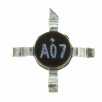
AD8250-EVALZ Analog Devices Inc, AD8250-EVALZ Datasheet - Page 2

AD8250-EVALZ
Manufacturer Part Number
AD8250-EVALZ
Description
BOARD EVALUATION AD8250
Manufacturer
Analog Devices Inc
Series
iCMOS®r
Specifications of AD8250-EVALZ
Channels Per Ic
1 - Single
Amplifier Type
Instrumentation
Output Type
Single-Ended
Slew Rate
25 V/µs
-3db Bandwidth
10MHz
Current - Output / Channel
37mA
Operating Temperature
-40°C ~ 85°C
Current - Supply (main Ic)
4.1mA
Voltage - Supply, Single/dual (±)
10 V ~ 30 V, ±5 V ~ 15 V
Board Type
Fully Populated
Utilized Ic / Part
AD8250
Lead Free Status / RoHS Status
Lead free / RoHS Compliant
AD8250
TABLE OF CONTENTS
Features .............................................................................................. 1
Applications....................................................................................... 1
General Description ......................................................................... 1
Functional Block Diagram .............................................................. 1
Revision History ............................................................................... 2
Specifications..................................................................................... 3
Absolute Maximum Ratings............................................................ 6
Pin Configuration and Function Descriptions............................. 7
Typical Performance Characteristics ............................................. 8
Theory of Operation ...................................................................... 15
REVISION HISTORY
11/10—Rev. A to Rev. B
Changes to Voltage Offset, Offset RTI V
Temperature Coefficient Parameter in Table 2............................. 3
Updated Outline Dimensions ....................................................... 22
5/08—Rev. 0 to Rev. A
Changes to Table 1............................................................................ 1
Changes to Table 2............................................................................ 3
Changes to Table 3............................................................................ 6
Added Figure 17; Renumbered Sequentially ................................ 9
Changes to Figure 23...................................................................... 10
Timing Diagram ........................................................................... 5
Maximum Power Dissipation ..................................................... 6
ESD Caution.................................................................................. 6
Gain Selection ............................................................................. 15
Power Supply Regulation and Bypassing ................................ 17
OS
, Average
Rev. B | Page 2 of 24
Applications..................................................................................... 20
Outline Dimensions ....................................................................... 22
Changes to Figure 24 to Figure 26................................................ 11
Added Figure 29 ............................................................................. 11
Changes to Figure 31...................................................................... 12
Deleted Figure 43 to Figure 46; Renumbered Sequentially ...... 14
Inserted Figure 45 and Figure 46.................................................. 14
Changes to Timing for Latched Gain Mode Section ................. 16
Changes to Layout Section and Coupling Noise Section.......... 18
Changes to Figure 59...................................................................... 21
1/07—Revision 0: Initial Version
Input Bias Current Return Path ............................................... 17
Input Protection ......................................................................... 17
Reference Terminal .................................................................... 18
Common-Mode Input Voltage Range ..................................... 18
Layout .......................................................................................... 18
RF Interference ........................................................................... 19
Driving an ADC ......................................................................... 19
Differential Output .................................................................... 20
Setting Gains with a Microcontroller ...................................... 20
Data Acquisition......................................................................... 21
Ordering Guide .......................................................................... 22


