AD8332-EVALZ Analog Devices Inc, AD8332-EVALZ Datasheet - Page 9
AD8332-EVALZ
Manufacturer Part Number
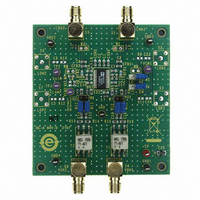
AD8332-EVALZ
Description
BOARD EVAL FOR AD8332
Manufacturer
Analog Devices Inc
Series
X-AMP®r
Specifications of AD8332-EVALZ
Channels Per Ic
1 - Single
Amplifier Type
Variable Gain
Output Type
Differential
Slew Rate
1100 V/µs
-3db Bandwidth
100MHz
Current - Output / Channel
45mA
Operating Temperature
-40°C ~ 85°C
Current - Supply (main Ic)
27.5mA
Voltage - Supply, Single/dual (±)
4.5 V ~ 5.5 V
Board Type
Fully Populated
Utilized Ic / Part
AD8332
Silicon Manufacturer
Analog Devices
Application Sub Type
Variable Gain Amplifier
Kit Application Type
Amplifier
Silicon Core Number
AD8332
Kit Contents
Board
Lead Free Status / RoHS Status
Lead free / RoHS Compliant


INITIALIZING ANALYZER MENUS
After the power and cabling have been set up, the system is
ready for initialization. A 1 MHz sine wave input signal is
recommended for this trial run. As a sanity check, observe the
waveform prior to digitization by probing JP12 and/or JP17
with a differential probe. Adjust generator and attenuator
settings for just under 2 V p-p to the ADC.
Initiate ADC Analyzer on the computer. When prompted for a
configuration file, select AD9238. This file will later require
modification and will be saved as AD8332 + AD9238.
Before FFT or time domain information can be displayed
correctly, you must configure the software for the hardware and
the clock frequency in use. In the upper left toolbar, left-click
the Config button, then FFT (the configuration data applies to
both the time domain and FFT displays.) In the Encode
Frequency (MSPS) box, adjust the MSPS to 20 if the on-board
20 MHz clock is used; otherwise enter the clock frequency of
the external clock source being used. In the Averages dialog
box, type 10. Clear the Twos Complement check box. Be sure
to enter the same Encode Frequency (MSPS) setting to
Channel A and Channel B. See Figure 7 for a display of the
FFT configuration setup. Save the revised configuration as a
new file—i.e., AD8332 + AD9238.
Figure 7. FFT Configuration Menu
Rev. 0 | Page 9 of 20
Analyzer displays both channels at once. To view a single VGA
channel, remove the input signal from the unused input of the
AD8332. For a first test, it’s a good idea to capture a waveform
in time domain. Left-click the Time Domain button (Figure 8),
and the display appears as in Figure 9.
The plot appears as a solid red rectangle. This is because it is
displaying each of the 16 k samples. To crop the display and
observe only a few cycles, left-click and drag the cursor
horizontally over a small portion of the waveform. Right-click
within the dialog box and a menu drops down. Right-click the
upper H-Zoom option, and the display appears as in Figure 10.
Figure 9. Initial Time Domain Display
Figure 10. Time Domain Waveform
Figure 8. Time Domain Button
EVAL-AD8332/AD9238
Related parts for AD8332-EVALZ
Image
Part Number
Description
Manufacturer
Datasheet
Request
R

Part Number:
Description:
BOARD EVAL FOR AD8332
Manufacturer:
Analog Devices Inc
Datasheet:

Part Number:
Description:
±1.7g Dual-Axis IMEMS Accelerometer Evaluation Board
Manufacturer:
Analog Devices Inc
Datasheet:

Part Number:
Description:
Inertial Sensor Evaluation System
Manufacturer:
Analog Devices Inc
Datasheet:
Part Number:
Description:
Manufacturer:
Analog Devices Inc
Datasheet:
Part Number:
Description:
Manufacturer:
Analog Devices Inc
Datasheet:
Part Number:
Description:
Manufacturer:
Analog Devices Inc
Datasheet:
Part Number:
Description:
Manufacturer:
Analog Devices Inc
Datasheet:
Part Number:
Description:
Manufacturer:
Analog Devices Inc
Datasheet:
Part Number:
Description:
Manufacturer:
Analog Devices Inc
Datasheet:
Part Number:
Description:
Manufacturer:
Analog Devices Inc
Datasheet:
Part Number:
Description:
Manufacturer:
Analog Devices Inc
Datasheet:
Part Number:
Description:
Manufacturer:
Analog Devices Inc
Datasheet:
Part Number:
Description:
Manufacturer:
Analog Devices Inc
Datasheet: