EK57 Cirrus Logic Inc, EK57 Datasheet - Page 2
EK57
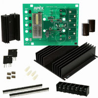
Manufacturer Part Number
EK57
Description
KIT EVAL FOR MP108FD/MP111FD
Manufacturer
Cirrus Logic Inc
Series
Apex Precision Power™r
Specifications of EK57
Channels Per Ic
1 - Single
Amplifier Type
Power
Output Type
Single-Ended
Board Type
Bare (Unpopulated)
Utilized Ic / Part
MP108FD, MP111FD
Product
Amplifier Modules
Description/function
Audio Amplifiers
For Use With/related Products
MP108FD, MP111FD
Lead Free Status / RoHS Status
Contains lead / RoHS non-compliant
Operating Temperature
-
Current - Output / Channel
-
Voltage - Supply, Single/dual (±)
-
-3db Bandwidth
-
Slew Rate
-
Current - Supply (main Ic)
-
Lead Free Status / RoHS Status
Lead free / RoHS Compliant, Contains lead / RoHS non-compliant
Other names
598-1470
EK57
EK57


ABSOLUTE MAXIMUM RATINGS
NOTES: 1. Unless otherwise noted: T
MP108 • MP108A
SPECIFICATIONS
PARAMETER
INPUT
OFFSET VOLTAGE
OFFSET VOLTAGE vs. temperature
OFFSET VOLTAGE vs. supply
BIAS CURRENT, initial
BIAS CURRENT vs. supply
OFFSET CURRENT, initial
INPUT RESISTANCE, DC
INPUT CAPACITANCE
COMMON MODE VOLTAGE RANGE
COMMON MODE VOLTAGE RANGE
COMMON MODE REJECTION, DC
NOISE
GAIN
OPEN LOOP @ 15Hz
GAIN BANDWIDTH PRODUCT @ 1MHz C
PHASE MARGIN
OUTPUT
VOLTAGE SWING
VOLTAGE SWING
VOLTAGE SWING
VOLTAGE SWING
CURRENT, continuous, DC
SLEW RATE, A
SETTLING TIME, to 0.1%
RESISTANCE
POWER BANDWIDTH 180V
POWER SUPPLY
VOLTAGE
CURRENT, quiescent
THERMAL
RESISTANCE, AC, junction to case
RESISTANCE, DC, junction to case
RESISTANCE, junction to air
TEMPERATURE RANGE, case
2
2. Long term operation at the maximum junction temperature will result in reduced product life. Derate internal power dissipation
3. Doubles for every 10°C of case temperature increase.
4. +V
5. Rating applies if the output current alternates between both output transistors at a rate faster than 60Hz.
6. Power supply voltages +V
is typical rating.
to achieve high MTBF.
supply voltages to the input stages.
V
S
= -20
and -V
3
S
denote the positive and negative supply voltages to the output stage. +V
P-P
5
C
B
=25°C, compensation C
and -V
TEST CONDITIONS
Full temperature range
1MHz bandwidth, 1kΩ R
R
Full temperature range
I
I
I
I
C
2V Step
No load, DC
C
Full temperature range, f ≤ 60Hz
Full temperature range, f < 60Hz
Full temperature range
O
O
O
O
L
C
C
C
= 10A
= -10A
= 10A, +V
= -10A, -V
= 10KΩ, C
= 10pF
= 10pF
= 10pF, +V
B
must not be less than +V
B
B
C
= +V
S
= -V
= 10pF
= 100V, -V
S
S
-10V
+10V
1
C
=100pF, DC input specifications are value given, power supply voltage
SUPPLY VOLTAGE, +V
SUPPLY VOLTAGE, +V
SUPPLY VOLTAGE, -V
OUTPUT CURRENT, peak
POWER DISSIPATION, internal, DC
INPUT VOLTAGE
TEMPERATURE, pin solder, 10s
TEMPERATURE, junction
TEMPERATURE RANGE, storage
OPERATING TEMPERATURE, case
P r o d u c t I n n o v a t i o n F r o m
S
S
= -100V
S
and -V
-V
+V
+V
-V
S
MIN
S
150
±15
S
-40
S
92
96
45
S
10
+ 5.1
respectively.
+ 10
- 1.6
- 10 +V
B
S
B
MP108
-V
to -V
2
TYP
±75
10
170
300
S
20
50
10
10
S
1
4
1
5
- 8.6
11
+ 7
S
B
and -V
+V
-V
MAX
±100
1.25
100
B
0.1
50
20
50
B
65
13
85
5
1
+ 15
- 15
B
denote the positive and negative
MIN
11
*
*
*
*
*
*
*
*
*
*
200V
+V
-V
12A, within SOA
100W
+V
225°C.
150°C.
-40 to 105°C.
-40 to 85°C.
S
MP108A
S
B
– 15V
+ 15V
to -V
TYP
*
*
*
*
*
*
*
*
*
*
*
*
*
*
B
6
6
MAX
70
30
3
*
*
*
*
*
*
*
*
*
*
*
MP108U
µV RMS
degrees
UNITS
µV/°C
°C/W
°C/W
°C/W
µV/V
pA/V
V/µS
MHz
kHz
mV
mA
pA
pA
pF
dB
dB
µS
°C
Ω
V
V
V
V
V
V
A
Ω
V
Related parts for EK57
Image
Part Number
Description
Manufacturer
Datasheet
Request
R

Part Number:
Description:
Development Kit
Manufacturer:
Cirrus Logic Inc
Datasheet:
Part Number:
Description:
Development Kit
Manufacturer:
Cirrus Logic Inc
Datasheet:


Part Number:
Description:
High-efficiency PFC + Fluorescent Lamp Driver Reference Design
Manufacturer:
Cirrus Logic Inc
Datasheet:
Part Number:
Description:
Development Kit
Manufacturer:
Cirrus Logic Inc
Datasheet:
Part Number:
Description:
Development Kit
Manufacturer:
Cirrus Logic Inc
Datasheet:

Part Number:
Description:
Development Kit
Manufacturer:
Cirrus Logic Inc
Datasheet:
Part Number:
Description:
Development Kit
Manufacturer:
Cirrus Logic Inc
Datasheet:
Part Number:
Description:
Development Kit
Manufacturer:
Cirrus Logic Inc
Datasheet:
Part Number:
Description:
Development Kit
Manufacturer:
Cirrus Logic Inc
Datasheet:

Part Number:
Description:
EVALUATION BOARD FOR CS8427
Manufacturer:
Cirrus Logic Inc
Datasheet:

Part Number:
Description:
BOARD EVAL FOR CS8416 RCVR
Manufacturer:
Cirrus Logic Inc
Datasheet:

Part Number:
Description:
EVALUATION BOARD FOR CS8420
Manufacturer:
Cirrus Logic Inc
Datasheet:

Part Number:
Description:
KIT DEVELOPMENT EP9315 ARM9
Manufacturer:
Cirrus Logic Inc
Datasheet:

Part Number:
Description:
KIT DEVELOPMENT EP9302 ARM9
Manufacturer:
Cirrus Logic Inc
Datasheet: