INTRODUCTION
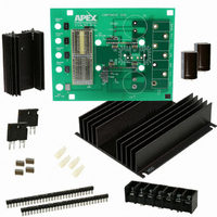
linear power amplifiers circuits using the MP108FD & MP111FD
pin out. With ample bread boarding areas it is flexible enough
to analyze a multitude of standard or proprietary circuit con-
figurations. Critical connections for power supply bypassing
are pre-wired. Components not usually readily available in
engineering labs are provided. External connection to the
evaluation kit can be made via the terminal block and terminal
pads at the edges of the circuit board. The terminal pads are
suitable for soldering standard banana jacks or direct wiring
of wires. Additionally, banana jacks and a BNC connector can
be inserted into the holes at the edge of the board and wired
to the numbered terminal pads.
BEFORE YOU GET STARTED
• All A pex Precision Power amplifiers should be handled using
• Do not change connections while the circuit is powered.
• Initially set all power supplies to the minimum operating
PARTS LIST
Ref
NA
NA
NA
NA
NA
C1,4,5,6 OX7R105KWN
TS1
C2,3
RLIM*
RLIM*
ASSEMBLY
MP108FD & MP111FD.
1. Note that each side of the circuit board is identified as either
2. Cut the MS11 into groups of 16 and 18 cage jacks and insert
EK57U
This easy-to-use kit provides a platform for the evaluation of
During assembly refer to Figure 2 and the data sheet for the
proper ESD precautions.
voltage allowed in the device data sheet.
the "component side" or "DUT side".
from the "DUT side" of the board. On the "component side"
of the board, solder all cage jacks having solder pads (7, 9,
10, 23, 24, 26, 29, and 31 have no solder pads). Make sure
the cage jacks are fully seated before soldering. Be careful
that solder does not flow into the cage jacks. Remove the
unsoldered cage jacks with the carrier strip segments.
http://www.cirrus.com
Evaluation Kit for MP108FD and MP111FD
Apex Part #
HS28
HS31
MS11
EVAL57
60SPG00004
TS02
EC03
CSR18
CSR19
EK57 MP108, MP111
P r o d u c t I n n o v a t i o n F r o m
P r o d u c t I n n o v a t i o n F r o m
Description/Vendor
Heat Sink
Heat Sink
Strip of 30 cage jacks
PC Board
Spacer Grommets/
Micro Plastics
1uF Cap/
Novacap
1825B105K201N
Terminal Strip
680uF 200V/
United Chemi-Con
KMH200VN681M25MX40T2
0.050 Ohm Resistor/
Isotek PBV-R050-1
0.100 Ohm Resistor/
Isotek PBV-R100-1
Copyright © Cirrus Logic, Inc. 2009
(All Rights Reserved)
Qty
1
1
2
1
4
4
1
2
1
1
3. Solder the surface mount capacitors at C1, C4, C5, and C6
4. Low ohm value resistors are provided with this evaluation
5. Mount the HS28 heat sink to the PCB and solder the mount-
6. Apply a thin layer of thermal grease on the back of the
7. Mount the electrolytic capacitors at C2 and C3 from the
8. Mount the terminal strip to the "component side" of the PCB.
9. Mount and wire the banana jacks and BNC connector (nei-
10. Mount other components to complete your application
11. From the "DUT side" of the PCB snap the spacer- grom-
12. Apply a thin, uniform layer of thermal grease to the amplifier;
13. Attach the amplifier to the heatsink with 4-40x½’ male-
14. Place the PCB assembly on the heatsink/amplifier assembly
on the "component side" of the board.
kit: 0.050 ohm and 0.100 ohm. These are used to implement
current limiting in the output circuit. Select the value most
appropriate for your application. Refer to the product data
sheet to determine which resistor value you should use.
ing tabs of the heat sink.
chosen current limiting sense resistor, insert the resistor
into the PCB and mount the resistor to the HS28 heat sink
using #4 screw and nut hardware (not supplied). Be sure
to cut off the excess resistor lead lengths.
"component side" of the PCB. Match the polarity markings
on the capacitor with the polarity markings on the PCB.
Be sure the capacitors have snapped into the PCB and
solder from the "DUT side" of the PCB. Be sure to fill the
holes with solder.
Make sure the terminal strip is fully seated and solder the
pins from the "DUT side" of the PCB. Be sure to fill the
mounting holes with solder.
ther supplied) to the PCB pads at locations 1-5 as needed
or desired.
circuit using the pads and holes provided.
mets into the holes at the four corners of the PCB. Notice
that the holes are slightly rectangular and match the spacer-
grommet's long and short sides to the holes in the PCB.
a straight edge may be useful here. Position the amplifier
over the mounting holes in the heatsink. Firmly push the
amplifier onto the heatsink while slightly rotating the ampli-
fier back and forth, ending with the mounting holes of the
amplifier over the mounting holes in the heatsink.
female hex spacers (not supplied). These spacers serve
as alignment pins and aide in the assembly of the PCB to
the heatsink. Alternatively, use 4-40x¼’ machine screws
to mount the amplifier to the heatsink. Do not over-tighten
the spacers or screws as this provides no thermal benefit
and may break the hardware.
so that the hex spacers come through the aligning holes
near the corners of the amplifier location in the PCB. Care-
fully lower the PCB assembly until the pins of the amplifier
engage the cage jacks. Alternately, sight through the align-
ing holes in the PCB and match-up the PCB to the screws
used to mount the amplifier. In either case be sure the pins
of the amplifier are engaged with the cage jacks and then
continue pushing the PCB assembly in the area between
APEX − EK57UREVC
EK57
MAY 2009
EK57
1