MCP6V01RD-TCPL Microchip Technology, MCP6V01RD-TCPL Datasheet - Page 27
MCP6V01RD-TCPL
Manufacturer Part Number
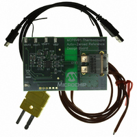
MCP6V01RD-TCPL
Description
REF DESIGN THERMCPL FOR MCP6V01
Manufacturer
Microchip Technology
Datasheets
1.MCP6V01RD-TCPL.pdf
(44 pages)
2.MCP6V01RD-TCPL.pdf
(30 pages)
3.MCP6V03-ESN.pdf
(40 pages)
Specifications of MCP6V01RD-TCPL
Channels Per Ic
1 - Single
Amplifier Type
Chopper (Zero-Drift)
Output Type
Rail-to-Rail
Slew Rate
0.5 V/µs
Current - Output / Channel
22mA
Operating Temperature
-40°C ~ 125°C
Voltage - Supply, Single/dual (±)
1.8 V ~ 5.5 V
Board Type
Fully Populated
Utilized Ic / Part
MCP6V01
Silicon Manufacturer
Microchip
Silicon Core Number
MCP6V01
Kit Application Type
Sensing - Temperature
Application Sub Type
Temperature Sensor
Processor To Be Evaluated
MCP6V01
Lead Free Status / RoHS Status
Lead free / RoHS Compliant
-3db Bandwidth
-
Current - Supply (main Ic)
-
Lead Free Status / Rohs Status
Lead free / RoHS Compliant


4.4.2
The ratiometric circuit in
wire RTD. It corrects for the sensor’s wiring resistance
by subtracting the voltage across the middle R
top R1 does not change the output voltage; it balances
the op amp inputs. Failure (open) of the RTD is
detected by an out of range voltage.
FIGURE 4-15:
The voltages at the input of the ADC can be calculated
with the following:
4.4.3
Figure 4-16
and temperature sensor used in a thermocouple
application. The type K thermocouple senses the
temperature at the hot junction (T
voltage at V
© 2008 Microchip Technology Inc.
Where:
R
R
R
V
V
R
100Ω
W
W
W
V
V
CM
DM
V
G
RTD
W
V
V
B
T
RTD
G
DM
CM
W
1
RTD SENSOR
THERMOCOUPLE SENSOR
shows a simplified diagram of an amplifier
proportional to T
=
=
=
=
=
=
=
=
=
10 nF
10 nF
1
G
G
V
------------------------------------------------------------------------------
V
T
+
RTD
RTD
DD
+
2 R
Voltage at the top of R
Voltage at the bottom of R
Voltage across top and middle
R
ADC’s common mode input
ADC’s differential mode input
R
20 kΩ
R
20 kΩ
V
⋅
(
W
–
T
B
V
RTD Sensor.
B
’s
1 µF
R
2.49 kΩ
2.49 kΩ
T
3
+
Figure 4-15
3
2.49 kΩ
2.49 kΩ
–
⁄
(
R
R
R
⁄
V
G
R
2
1
1
B
1
RTD
HJ
)
2
+
(in °C). The amplifier’s
G
+
HJ
W
R
2.55 kΩ
R
2.55 kΩ
1 G
100 kΩ
100 kΩ
100 nF
100 nF
), and produces a
conditions a three
V
2
2
–
R
R
W
3
3
½ MCP6V02
½ MCP6V02
W
)V
RTD
W
RTD
3 kΩ
3 kΩ
ADC
W
V
. The
DD
gain is is set so that V
the output of a temperature sensor, which produces a
voltage proportional to the temperature (in °C) at the
cold junction (T
that V
EQUATION 4-5:
FIGURE 4-16:
Simplified Circuit.
Figure 4-17
this circuit. The dashed red arrow indicates a thermally
conductive connection between the thermocouple and
the MCP9700A; it needs to be very short and have low
thermal resistance.
FIGURE 4-17:
The MCP9700A senses the temperature at its physical
location. It needs to be at the same temperature as the
cold junction (T
V
V
V
V
≈ (10 mV/°C) (T
(hot junction
MCP9700A
1
2
3
4
at T
(cold junction
MCP1541
Type K
≈ T
= (1.00V)
= T
= 250V
4
40 µV/°C
Type K
Thermocouple
V
V
is 0.50V when T
HJ
HJ
CJ
DD
DD
)
at T
(40 µV/°C)
(10 mV/°C) + (0.50V)
shows a more complete implementation of
1
V
+ (V
CJ
1
CJ
CJ
)
), and with a 0.50V offset. V
), and produces V
2
HJ
4.100R
R/250
R/250
– V
MCP6V01/2/3
4
R
– T
V
V
V
/T
Thermocouple Sensor;
Thermocouple Sensor.
3
1
2
3
HJ
)
HJ
CJ
– T
) + (0.50V)
is 10 mV/°C. V
R/250
R/250
0.5696R
CJ
R
R
C
C
R
is 0°C.
MCP6V01
3
DS22058B-page 27
(Figure
C
C
R
R
3 kΩ
3
MCP6V01
represents
2
4-14).
is set so
V
V
4
4
Related parts for MCP6V01RD-TCPL
Image
Part Number
Description
Manufacturer
Datasheet
Request
R

Part Number:
Description:
Manufacturer:
Microchip Technology Inc.
Datasheet:
Part Number:
Description:
Manufacturer:
Microchip Technology Inc.
Datasheet:
Part Number:
Description:
Manufacturer:
Microchip Technology Inc.
Datasheet:
Part Number:
Description:
Manufacturer:
Microchip Technology Inc.
Datasheet:
Part Number:
Description:
Manufacturer:
Microchip Technology Inc.
Datasheet:
Part Number:
Description:
Manufacturer:
Microchip Technology Inc.
Datasheet:
Part Number:
Description:
Manufacturer:
Microchip Technology Inc.
Datasheet:
Part Number:
Description:
Manufacturer:
Microchip Technology Inc.
Datasheet: