MCP6V01RD-TCPL Microchip Technology, MCP6V01RD-TCPL Datasheet
MCP6V01RD-TCPL
Specifications of MCP6V01RD-TCPL


Related parts for MCP6V01RD-TCPL

MCP6V01RD-TCPL Summary of contents
Page 1
... Thermocouple Auto-Zeroed © 2008 Microchip Technology Inc. MCP6V01 Reference Design DS51738B ...
Page 2
... PowerMate, PowerTool, REAL ICE, rfLAB, Select Mode, Total Endurance, WiperLock and ZENA are trademarks of Microchip Technology Incorporated in the U.S.A. and other countries. SQTP is a service mark of Microchip Technology Incorporated in the U.S.A. All other trademarks mentioned herein are property of their respective companies. ...
Page 3
... A.4 Board - Top Metal Layer .............................................................................. 19 A.5 Board - Metal Layer 2 .................................................................................. 20 A.6 Board - Metal Layer 3 .................................................................................. 20 A.7 Board - Bottom Silk Layer (Bottom View) .................................................... 21 A.8 Board - Bottom Layer ................................................................................... 21 Appendix B. Bill Of Materials (BOM) Worldwide Sales and Service .................................................................................... 26 © 2008 Microchip Technology Inc. MCP6V01 THERMOCOUPLE Table of Contents DS51738B-page iii ...
Page 4
... MCP6V01 Thermocouple Auto-Zeroed Reference Design NOTES: DS51738B-page iv © 2008 Microchip Technology Inc. ...
Page 5
... Appendix A. “Schematic and Layout” – Shows the schematic and board layouts for the MCP6V01 Thermocouple Auto-Zeroed Reference Design. • Appendix B. “Bill Of Materials (BOM)” – Lists the parts used to build the MCP6V01 Thermocouple Auto-Zeroed Reference Design. © 2008 Microchip Technology Inc. MCP6V01 THERMOCOUPLE Preface NOTICE TO CUSTOMERS ® ...
Page 6
... Optional arguments mcc18 [options] file [options] Choice of mutually exclusive errorlevel {0|1} arguments selection Replaces repeated text var_name [, var_name...] Represents code supplied by void main (void) user { ... } © 2008 Microchip Technology Inc. Examples ® IDE User’s Guide ...
Page 7
... Microchip consultant program member listing • Business of Microchip – Product selector and ordering guides, latest Microchip press releases, listing of seminars and events, listings of Microchip sales offices, distributors and factory representatives © 2008 Microchip Technology Inc. Preface DS51738B- page 3 ...
Page 8
... Technical support is available through the web site at: http://support.microchip.com DOCUMENT REVISION HISTORY Revision B (December 2008) • Updated the Bottom Metal Layer print. • Updated Product Review. Revision A (May 2008) • Initial Release of this Document. DS51738B- page 4 © 2008 Microchip Technology Inc. ...
Page 9
... INTRODUCTION The MCP6V01 Thermocouple Auto-Zeroed Reference Design is described by the following: • Assembly # : 114-00169 • Order # : MCP6V01RD-TCPL • Name: MCP6V01 Thermocouple Auto-Zeroed Reference Design Board Items discussed in this chapter include: • MCP6V01 Thermocouple Auto-Zeroed Reference Design Board Kit Contents • MCP6V01 Thermocouple Auto-Zeroed Reference Design Board Description • ...
Page 10
... DS51738B- page 6 (4.1V) to the internal 10-Bit ADC of the REF is the internal comparator voltage reference of PIC18F2550, which is . SHIFT ) and OS © 2008 Microchip Technology Inc. ...
Page 11
... Figure 1-2 shows the function block diagram of the MCP6V01 Thermocouple Auto-Zeroed Reference Design. SDA SCKL ALERT Cold Junction Compensation MCP9800 Temp. Sensor FIGURE 1-2: Auto-Zeroed Reference Design. © 2008 Microchip Technology Inc. PC (Thermal Management Software) USB PIC18F2550 (USB) Microcontroller 2 CV 10-Bit ADC Module I C Port REF ...
Page 12
... Analog Sensing Circuit Diagram of the MCP6V01 Thermocouple (R9 and R10) OUT1 Order RC Order RC Low-Pass Filter Low-Pass Filter R12 R12 R13 R13 499O 499O 499O 499O OUT1 OUT1 OUT2 OUT2 0.1 µF 0.1 µF 0.1 µF 0.1 µF = 4.1V = 4.1V REF REF © 2008 Microchip Technology Inc. ...
Page 13
... Figure 1-4 shows the conceptual diagram of the 4.1V 4.1V 4.1V FIGURE 1-4: © 2008 Microchip Technology Inc. Operation Description through the buffer amplifier. V SHIFT values accurate to the 10-Bit ADC’s capability. The SHIFT (16 levels) subdivides input ranges REF , V and are not drawn to scale ...
Page 14
... Temperature range is from -100°C to +1000°C • Uses the MCP9800 Temperature Sensor for cold junction compensation • Uses the USB interface to transfer data to PC • 14-Bit Resolution, 10-Bit ADC • Test points for bench work DS51738B- page 10 © 2008 Microchip Technology Inc. ...
Page 15
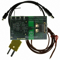
... MCP6V01 THERMOCOUPLE AUTO-ZEROED REFERENCE DESIGN SETUP 1. Connect the type K thermocouple and the USB cable to the MCP6V01 Thermo- couple Auto-Zeroed Reference Design. An exploded view is shown in the Figure 2-1. FIGURE 2-1: © 2008 Microchip Technology Inc. MCP6V01 THERMOCOUPLE MCP6V01 Thermocouple Auto-Zeroed Reference Design Setup. DS51738B-page 11 ...
Page 16
... Thermocouple Instrumentation GUI Using MCP6V01 panel, as indicated in Figure 2-2. Otherwise, the software will show the Hardware Not Detected message box, as indicated in Figure 2-3. FIGURE 2-2: Thermocouple Instrumentation GUI Using MCP6V01. FIGURE 2-3: Hardware Not Detected Message Box. DS51738B-page 12 © 2008 Microchip Technology Inc. ...
Page 17
... Set Up the MCP9800 Temperature Sensor Configuration 1. Click the MCP9800 Setup tab. 2. The MCP9800 Configuration can be modified from the default values. 3. Click the Update Temp. button to complete the modifications. FIGURE 2-4: MCP9800 Setup. © 2008 Microchip Technology Inc. Installation and Operation DS51738B-page 13 ...
Page 18
... MCP6V01 Thermocouple Auto-Zeroed Reference Design 2.4.2 Set Up the Thermocouple Configuration 1. Click the Thermocouple Setup tab. 2. Enable thermocouple is selected as default. Enable Calibration also can be selected. 3. Click the Update button to complete the setup. . FIGURE 2-5: Thermocouple setup. DS51738B-page 14 © 2008 Microchip Technology Inc. ...
Page 19
... Customize the Realtime Data Aquisition 1. Double click on the region of the stipchart to customize the Realtime Data Aqui- sition. . FIGURE 2-6: © 2008 Microchip Technology Inc. Installation and Operation Realtime Data Aquisition Customization. DS51738B-page 15 ...
Page 20
... MCP6V01 Thermocouple Auto-Zeroed Reference Design 2.4.3.1 START THE REALTIME DATA AQUISITION 1. Click the PLAY button to start the Realtime Data Aquisition. FIGURE 2-7: Start Realtime Data Aquisition. DS51738B-page 16 © 2008 Microchip Technology Inc. ...
Page 21
... Board – Top Silk Layer • Board – Top Metal Layer • Board – Metal Layer 2 • Board – Metal Layer 3 • Board – Bottom Silk Layer • Board – Bottom Metal Layer © 2008 Microchip Technology Inc. MCP6V01 THERMOCOUPLE DS51738B-page 17 ...
Page 22
... MCP6V01 Thermocouple Auto-Zeroed Reference Design A.2 BOARD - SCHEMATIC DS51738B-page 18 © 2008 Microchip Technology Inc. ...
Page 23
... A.3 BOARD - TOP SILK LAYER A.4 BOARD - TOP METAL LAYER © 2008 Microchip Technology Inc. Schematic and Layout DS51738B-page 19 ...
Page 24
... MCP6V01 Thermocouple Auto-Zeroed Reference Design A.5 BOARD - METAL LAYER 2 A.6 BOARD - METAL LAYER 3 DS51738B-page 20 © 2008 Microchip Technology Inc. ...
Page 25
... A.7 BOARD - BOTTOM SILK LAYER (BOTTOM VIEW) A.8 BOARD - BOTTOM METAL LAYER © 2008 Microchip Technology Inc. Schematic and Layout DS51738B-page 21 ...
Page 26
... MCP6V01 Thermocouple Auto-Zeroed Reference Design NOTES: DS51738B-page 22 © 2008 Microchip Technology Inc. ...
Page 27
... R12, R13 RES 499 OHM 1/8W 1% 0805 SMD Note 1: The components listed in this Bill of Materials are representative of the PCB assembly. The released BOM used in manufacturing uses all RoHS-compliant components. © 2008 Microchip Technology Inc. MCP6V01 THERMOCOUPLE Description Manufacturer ® Panasonic - ECG ...
Page 28
... Panasonic - ECG OMEGA Keystone Electronics Microchip Technology Inc. PIC18F2550-I/SO Microchip Technology Inc. MCP1541T-I/TT Microchip Technology Inc. MCP9800A0T-M/OTG Microchip Technology Inc. MCP6001T-I/OT Microchip Technology Inc. MCP6V01T-E/SN CTS-Frequency Controls Part Number ERJ-3EKF1001V 5SRTC-TT-K-24-36 (5 Pcs. Per Pack) ® 5016 ATS200SM © 2008 Microchip Technology Inc. ...
Page 29
... NOTES: © 2008 Microchip Technology Inc. Bill Of Materials (BOM) DS51738B-page 25 ...
Page 30
... Fax: 886-3-572-6459 Taiwan - Kaohsiung Tel: 886-7-536-4818 Fax: 886-7-536-4803 Taiwan - Taipei Tel: 886-2-2500-6610 Fax: 886-2-2508-0102 Thailand - Bangkok Tel: 66-2-694-1351 Fax: 66-2-694-1350 © 2008 Microchip Technology Inc. EUROPE Austria - Wels Tel: 43-7242-2244-39 Fax: 43-7242-2244-393 Denmark - Copenhagen Tel: 45-4450-2828 Fax: 45-4485-2829 France - Paris Tel: 33-1-69-53-63-20 ...