NCP102MBGEVB ON Semiconductor, NCP102MBGEVB Datasheet - Page 3
NCP102MBGEVB
Manufacturer Part Number
NCP102MBGEVB
Description
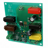
EVAL BOARD FOR NCP102MBG
Manufacturer
ON Semiconductor
Specifications of NCP102MBGEVB
Design Resources
NCP102 Demo Brd BOM NCP102MBGEVB Gerber Files NCP102 EVB Schematic
Channels Per Ic
1 - Single
Voltage - Output
1.2V
Current - Output
3A
Voltage - Input
1.8V
Regulator Type
Positive Fixed
Board Type
Fully Populated
Utilized Ic / Part
NCP102
Lead Free Status / RoHS Status
Lead free / RoHS Compliant
Operating Temperature
-
Lead Free Status / Rohs Status
Lead free / RoHS Compliant
For Use With/related Products
NCP102MBG
Other names
NCP102MBGEVBOS


No-Load Regulation and Enable Function
Full-Load Regulation and Enable Function
1/22/08
6.
7.
8.
1.
2.
3.
4.
5.
6.
7.
8.
9.
1.
2.
3.
4.
5.
6.
7.
8.
Adjust the Vcc supply to 5.0VDC while observing DMM 1
(not the indicator on the DC supply).
Adjust the Vin supply to 1.800VDC while observing DMM 2
(not the indicator on the DC supply).
Disable the electronic load so that it is neither sinking nor
sourcing current.
Verify that Vout (DMM 3) equals zero VDC.
Temporarily disconnect the banana cable connected to
“N_Enable”, or reduce the “N_Enable” supply to zero Volts.
Verify that Vin (DMM 2) equals 1.800VDC, +/- 2%
(1.764VDC to 1.836VDC).
Readjust the Vin supply if necessary.
Verify that Vout (DMM 3) equals 1.200VDC, +/- 2%
(1.176VDC to 1.224VDC).
Reconnect the banana cable to “N_Enable”, or adjust the
“N_Enable” supply output to 4.5VDC.
If Vcc= 12.0VDC (DMM 1), go to Full-Load Regulation and
Enable Function, below.
Adjust the Vcc supply to 12.0VDC, as indicated on DMM 1.
Repeat steps 1 through 7 of this section.
While observing the front panel indicator on the electronic
load, adjust it to sink 3.5ADC from the demonstration board
Vout terminal.
Enable the electronic load.
Verify that Vout (DMM 3) equals zero VDC.
Temporarily disconnect the banana cable connected to
“N_Enable”, or reduce the “N_Enable” supply to zero Volts.
Verify that Vin (DMM 2) equals 1.800VDC, +/- 2%
(1.764VDC to 1.836VDC).
Readjust the Vin supply if necessary.
Verify that Vout (DMM 3) equals 1.200VDC, +/- 2%
(1.176VDC to 1.224VDC).
Reconnect the banana cable to “N_Enable”, or adjust the
“N_Enable” supply output to 4.5VDC.
NCP102 Demonstration Board Test Procedure
3 of 4
REV 1
Related parts for NCP102MBGEVB
Image
Part Number
Description
Manufacturer
Datasheet
Request
R

Part Number:
Description:
ON Semiconductor [VOLTAGE REGULATOR]
Manufacturer:
ON Semiconductor
Datasheet:
Part Number:
Description:
357-036-542-201 CARDEDGE 36POS DL .156 BLK LOPRO
Manufacturer:
ON Semiconductor
Datasheet:
Part Number:
Description:
357-036-542-201 CARDEDGE 36POS DL .156 BLK LOPRO
Manufacturer:
ON Semiconductor
Datasheet:
Part Number:
Description:
357-036-542-201 CARDEDGE 36POS DL .156 BLK LOPRO
Manufacturer:
ON Semiconductor
Datasheet:
Part Number:
Description:
357-036-542-201 CARDEDGE 36POS DL .156 BLK LOPRO
Manufacturer:
ON Semiconductor
Datasheet:
Part Number:
Description:
357-036-542-201 CARDEDGE 36POS DL .156 BLK LOPRO
Manufacturer:
ON Semiconductor
Datasheet:
Part Number:
Description:
357-036-542-201 CARDEDGE 36POS DL .156 BLK LOPRO
Manufacturer:
ON Semiconductor
Datasheet:
Part Number:
Description:
357-036-542-201 CARDEDGE 36POS DL .156 BLK LOPRO
Manufacturer:
ON Semiconductor
Datasheet:
Part Number:
Description:
357-036-542-201 CARDEDGE 36POS DL .156 BLK LOPRO
Manufacturer:
ON Semiconductor
Datasheet:
Part Number:
Description:
357-036-542-201 CARDEDGE 36POS DL .156 BLK LOPRO
Manufacturer:
ON Semiconductor
Datasheet:
Part Number:
Description:
357-036-542-201 CARDEDGE 36POS DL .156 BLK LOPRO
Manufacturer:
ON Semiconductor
Datasheet:
Part Number:
Description:
Manufacturer:
ON Semiconductor
Datasheet:
Part Number:
Description:
Manufacturer:
ON Semiconductor
Datasheet:
Part Number:
Description:
Manufacturer:
ON Semiconductor
Datasheet: