TO263-5EV-VREG Microchip Technology, TO263-5EV-VREG Datasheet - Page 11
TO263-5EV-VREG
Manufacturer Part Number
TO263-5EV-VREG
Description
EVAL BOARD VREG TO220-5/TO263-5
Manufacturer
Microchip Technology
Datasheet
1.TO263-5EV-VREG.pdf
(20 pages)
Specifications of TO263-5EV-VREG
Channels Per Ic
1 - Single
Regulator Type
Positive Fixed & Adjustable
Board Type
Partially Populated
Utilized Ic / Part
TO-220-5 & TO-263-5 (D²Pak-5) Packages
Silicon Manufacturer
Microchip
Application Sub Type
Voltage Regulator
Kit Application Type
Power Management - Voltage Regulator
Silicon Core Number
MCP1790, MCP1791, MCP1825, MCP1826, MCP1827
Lead Free Status / RoHS Status
Lead free / RoHS Compliant
Current - Output
-
Voltage - Output
-
Voltage - Input
-
Operating Temperature
-
Lead Free Status / Rohs Status
Lead free / RoHS Compliant


2.1
2.2
2.3
© 2009 Microchip Technology Inc.
INTRODUCTION
FEATURES
GETTING STARTED
Chapter 2. Installation and Operation
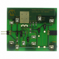
The TO220-5 / TO263-5 Voltage Regulator Evaluation Board is designed to be used to
facilitate the evaluation of Microchip’s voltage regulators or to be used as a standalone
voltage regulator board. Jumpers have been placed on the board to facilitate testing of
specific voltage regulator parameters.
The TO220-5 / TO263-5 Voltage Regulator Evaluation Board kit comes with a 1 µF
ceramic input and output capacitor soldered to the board. The board has two
unpopulated resistor locations that may be used for loads.
The TO220-5 / TO263-5 Voltage Regulator Evaluation Board has the following
features:
• Input and Output headers for future connection to Line Step and Load Step
• Ample testpoints to attach multimeters, power supplies, and loads
• Jumper to select ground current measurement
• Jumpers to connect output load resistors
• Jumper to connect input capacitor to circuit
The TO220-5 / TO263-5 Voltage Regulator Evaluation Board is fully assembled and
tested. All that is required for operating is a user supplied voltage regulator and a
supply voltage source. Some of the tests that may be completed using the TO220-5 /
TO263-5 Voltage Regulator Evaluation Board shall now be described.
2.3.1
When measuring ground current, jumper JP3 should be removed, otherwise leave
jumper JP3 on. To measure ground current, perform the following steps:
1. Add desired load resistors to R5 and R6.
2. Remove jumpers JP3, JP4, and JP5.
3. Connect an Ampere Meter across testpoints TP6(+) and TP7(-). Select the
4. Connect a voltmeter across testpoints TP9(+) and TP10(-).
5. Add jumper JP1.
6. Apply source voltage to testpoints TP1(+) and TP2(-).
7. Verify the voltage across testpoints TP9 and TP10 is within the expected range
8. Read the Ground Current directly from the ampere meter connected to testpoints
modules
appropriate meter scale for the device being evaluated.
of the device being tested.
TP6 and TP7.
Ground Current and Quiescent Current
TO220-5 / TO263-5 VOLTAGE
REGULATOR EVALUATION
BOARD USER’S GUIDE
DS51817A-page 7
Related parts for TO263-5EV-VREG
Image
Part Number
Description
Manufacturer
Datasheet
Request
R

Part Number:
Description:
Manufacturer:
National Semiconductor
Datasheet:
Part Number:
Description:
Manufacturer:
National Semiconductor
Datasheet:
Part Number:
Description:
Manufacturer:
National Semiconductor
Datasheet:
Part Number:
Description:
Manufacturer:
National Semiconductor
Datasheet:


Part Number:
Description:
TO263
Manufacturer:
Infineon Technologies AG
Datasheet:
Part Number:
Description:
TO263
Manufacturer:
Infineon Technologies AG
Datasheet:


Part Number:
Description:
TO263
Manufacturer:
Infineon Technologies AG
Datasheet: