TO263-5EV-VREG Microchip Technology, TO263-5EV-VREG Datasheet - Page 10
TO263-5EV-VREG
Manufacturer Part Number
TO263-5EV-VREG
Description
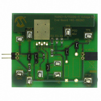
EVAL BOARD VREG TO220-5/TO263-5
Manufacturer
Microchip Technology
Datasheet
1.TO263-5EV-VREG.pdf
(20 pages)
Specifications of TO263-5EV-VREG
Channels Per Ic
1 - Single
Regulator Type
Positive Fixed & Adjustable
Board Type
Partially Populated
Utilized Ic / Part
TO-220-5 & TO-263-5 (D²Pak-5) Packages
Silicon Manufacturer
Microchip
Application Sub Type
Voltage Regulator
Kit Application Type
Power Management - Voltage Regulator
Silicon Core Number
MCP1790, MCP1791, MCP1825, MCP1826, MCP1827
Lead Free Status / RoHS Status
Lead free / RoHS Compliant
Current - Output
-
Voltage - Output
-
Voltage - Input
-
Operating Temperature
-
Lead Free Status / Rohs Status
Lead free / RoHS Compliant


TO220-5 / TO263-5 Voltage Regulator Evaluation Board User’s Guide
1.3
DS51817A-page 6
WHAT THE TO220-5 / TO263-5 VOLTAGE REGULATOR EVALUATION
BOARD KIT INCLUDES.
1.2.3
Jumper JP2 allows the user to select the Shutdown (SHDN) pin voltage level. The
voltage level may be set to V
jumper. When the jumper is not connecting pins 1 and 2 or pins 2 and 3 of JP2, the
voltage level may be set by attaching an external signal to TP5. This allows the user to
enable, disable, or pulse the shutdown pin of the device.
The board comes with R1 populated with a 10 kΩ resistor.
1.2.4
Jumper JP3 allows measurement of ground current. When a current meter is
connected to TP6 and TP7 and jumper JP3 is removed, the ground current of the
device may be measured.
1.2.5
For Adjustable Output Voltage devices, R2 and R3 may be populated with appropriate
values to provide the desired output voltage.
The board comes with R2 populated with a 69.8 kΩ resistor.
1.2.6
For devices with a Power Good (PWRGD) output, either R2 or R4 is populated
depending on the desired pullup source voltage.
R2 selects V
R4 selects V
The board comes with R2 populated with a 69.8 kΩ resistor.
1.2.7
R5 and R6 may be populated with the desired load resistor values for the device being
evaluated. Jumper JP4 connects R5 to the device output. Jumper JP5 connects R6 to
the device output.
1.2.8
C2 may be populated with the desired output capacitance. By default, C2 is populated
with a 1 µF, 6.3V, XR7 ceramic capacitor.
1.2.9
J1 or TP1 and TP2 are connected to the user’s power supply.
This TO220-5 / TO263-5 Voltage Regulator Evaluation Board kit includes:
• TO220-5 / TO263-5 Voltage Regulator Evaluation Board (102-00203, Qty 2)
• Important Information “Read First”
Shutdown Control
Ground Current Measurement
Voltage Adjust
Power Good (PWRGD)
Load Resistor
Output Capacitor
Power Supply
OUT
IN
as the pullup source voltage.
as the pullup source voltage.
IN
, GND, or open, depending on the placement of the JP2
© 2009 Microchip Technology Inc.
Related parts for TO263-5EV-VREG
Image
Part Number
Description
Manufacturer
Datasheet
Request
R

Part Number:
Description:
Manufacturer:
National Semiconductor
Datasheet:
Part Number:
Description:
Manufacturer:
National Semiconductor
Datasheet:
Part Number:
Description:
Manufacturer:
National Semiconductor
Datasheet:
Part Number:
Description:
Manufacturer:
National Semiconductor
Datasheet:


Part Number:
Description:
TO263
Manufacturer:
Infineon Technologies AG
Datasheet:
Part Number:
Description:
TO263
Manufacturer:
Infineon Technologies AG
Datasheet:


Part Number:
Description:
TO263
Manufacturer:
Infineon Technologies AG
Datasheet: