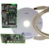
LP5526TLEV National Semiconductor, LP5526TLEV Datasheet - Page 3

LP5526TLEV
Manufacturer Part Number
LP5526TLEV
Description
BOARD EVAL LP5526 LMU LED DRIVER
Manufacturer
National Semiconductor
Series
PowerWise®r
Specifications of LP5526TLEV
Current - Output / Channel
150mA
Outputs And Type
2 (25mA), 1 (150mA)
Voltage - Output
20 V
Features
Camera Flash, Dimmable, RGB Controller
Voltage - Input
3 ~ 5.5V
Utilized Ic / Part
LP5526
Lead Free Status / RoHS Status
Not applicable / Not applicable
BOOST TAB
COLOR LEDS TAB
Figure 4. Color LEDs Tab
Figure 3. Boost Tab
20198203
20198214
3
In this tab LP5526 boost converter can be enabled, and the
output voltage can be set from the pull-down menu. The in-
ternal active load can be enabled to eliminate pulse skipping
of the boost converter. Active load will consume some power
when the boost output current is small. It will decrease effi-
ciency at very light load conditions. See datasheet for boost
converter typical performance graphs.
In this tab are all RGB LED controls. RGB outputs are enabled
with 'RGB' selection box, every color output has also individ-
ual enable. 'RGB PWM' enables the internal PWM generation
and color selection. RGB outputs' mode can be selected ei-
ther 'Current sink', or 'Switch mode'. Default is 'Switch mode'.
In 'Switch mode' the outputs are low ohmic switches. 'Switch
mode' should be used only when external ballast resistors are
used in series with the LEDs.
With 'RGB color and bright' section it is possible to control the
RGB LED color with PWM. In overlapping mode color cannot
be selected. In the diagram the LED on/off times are present-
ed.
'RGB maximum' current can be selected for each output from
25% to 100%. Evaluation board resistor R23 and R27 limits
the maximum RGB current; default value 2.4 kΩ or 2.4 + 3.3
= 5.7 kΩ when jumper J26 is disconnected. Current limiting
function is active only if 'Current Sinks' is selected.
Remember that with Flash LED, only the Current Sink mode
should be used, NOT Switch mode since there is no current
limiting resistor in series with Flash LEDs. Switch mode
should be used only when RGB led is used and current lim-
iting resistors are not bypassed (jumpers J6-J8 off).
External PWM control can be enabled to each output. These
must be enabled, when the Flash function is used. Flash but-
ton forces GPIO[0]/PWM pin to high. It is active only when it
is kept pressed down, and will be low only after release the
Flash button. Remember to set USB PortA GPIO[0] as output
and set 'en pwm pin' from GPIO tab.
'Check bit' button can be used any time to read back the
'safety_set' bit value. The bit is set when safety function has
switched LED's off due to 1s timeout. 'safety_set' bit is read
automatically always when user pushes Flash button down
and also when it is released.
The 'R
quired R
calculation purposes only and does not control the current in
any way.
RGB
RGB
calculator' selection can be used to estimate re-
resistor value for the specific current. It is for
www.national.com


