LM3405XEVAL National Semiconductor, LM3405XEVAL Datasheet - Page 10
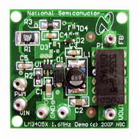
LM3405XEVAL
Manufacturer Part Number
LM3405XEVAL
Description
BOARD EVALUATION LM3405X
Manufacturer
National Semiconductor
Series
PowerWise®r
Specifications of LM3405XEVAL
Current - Output / Channel
1A
Outputs And Type
1, Non-Isolated
Voltage - Output
0.2 ~ 13.5 V
Features
Dimmable
Voltage - Input
3 ~ 15V
Utilized Ic / Part
LM3405
Kit Contents
Board, Datasheet
Svhc
No SVHC (15-Dec-2010)
Kit Features
Cycle-by-Cycle Current Limit,
Rohs Compliant
No
Lead Free Status / RoHS Status
Contains lead / RoHS non-compliant


www.national.com
threshold provides an upper limit for the LED current. LED
current overshoot is limited to 328mV/R1 by this comparator
during transients.
THERMAL SHUTDOWN
Thermal shutdown limits total power dissipation by turning off
the internal power switch when the IC junction temperature
exceeds 165°C. After thermal shutdown occurs, the power
switch does not turn on until the junction temperature drops
below approximately 150°C.
Design Guide
INDUCTOR (L1)
The Duty Cycle (D) can be approximated quickly using the
ratio of output voltage (V
The catch diode (D1) forward voltage drop and the voltage
drop across the internal NMOS must be included to calculate
a more accurate duty cycle. Calculate D by using the following
formula:
V
The diode forward drop (V
depending on the quality of the diode. The lower V
higher the operating efficiency of the converter.
The inductor value determines the output ripple current (Δi
as defined in Figure 2). Lower inductor values decrease the
size of the inductor, but increases the output ripple current.
An increase in the inductor value will decrease the output rip-
ple current. The ratio of ripple current to LED current is
optimized when it is set between 0.3 and 0.4 at 1A LED cur-
rent. This ratio r is defined as:
One must also ensure that the minimum current limit (1.2A)
is not exceeded, so the peak current in the inductor must be
calculated. The peak current (I
as:
When the designed maximum output current is reduced, the
ratio r can be increased. At a current of 0.2A, r can be made
as high as 0.7. The ripple ratio can be increased at lighter
loads because the net ripple is actually quite low, and if r re-
mains constant the inductor value can be made quite large.
An equation empirically developed for the maximum ripple
ratio at any current below 2A is:
Note that this is just a guideline.
The LM3405 operates at a high frequency allowing the use of
ceramic output capacitors without compromising transient re-
SW
can be approximated by:
r = 0.387 x I
V
I
SW
LPK
OUT
= I
= I
D1
) to input voltage (V
F
) can range from 0.3V to 0.7V
F
LPK
x R
+ Δi
OUT
) in the inductor is calculated
DS(ON)
L
-0.3667
/2
IN
):
D1
is, the
L
,
10
sponse. Ceramic capacitors allow higher inductor ripple with-
out significantly increasing LED current ripple. See the output
capacitor and feed-forward capacitor sections for more de-
tails on LED current ripple.
Now that the ripple current or ripple ratio is determined, the
inductance is calculated by:
where f
When selecting an inductor, make sure that it is capable of
supporting the peak output current without saturating. Induc-
tor saturation will result in a sudden reduction in inductance
and prevent the regulator from operating correctly. Because
of the operating frequency of LM3405, ferrite based inductors
are preferred to minimize core losses. This presents little re-
striction since the variety of ferrite based inductors is huge.
Lastly, inductors with lower series resistance (DCR) will pro-
vide better operating efficiency. For recommended inductor
selection, refer to Circuit Examples and Recommended In-
ductance Range in Table 1. Note that it is a good practice to
use small inductance value at light load (for example, I
0.2A) to increase inductor current ramp signal, such that noise
immunity is improved.
*Maximum over full range of V
**Small inductance improves stability without causing a significant increase
in LED current ripple.
INPUT CAPACITOR (C1)
An input capacitor is necessary to ensure that V
drop excessively during switching transients. The primary
specifications of the input capacitor are capacitance, voltage
rating, RMS current rating, and ESL (Equivalent Series In-
ductance). The input voltage rating is specifically stated by
the capacitor manufacturer. Make sure to check any recom-
mended deratings and also verify if there is any significant
change in capacitance at the operating input voltage and the
operating temperature. The input capacitor maximum RMS
input current rating (I
It can be shown from the above equation that maximum RMS
capacitor current occurs when D = 0.5. Always calculate the
RMS at the point where the duty cycle D, is closest to 0.5. The
ESL of an input capacitor is usually determined by the effec-
tive cross sectional area of the current path. A large leaded
1.0A
0.6A
0.2A
I
F
TABLE 1. Recommended Inductance Range
SW
Inductance Range and Inductor Current Ripple
is the switching frequency and I
Inductance
Inductance
Inductance
Δi
Δi
Δi
L
L
L
/ I
/ I
/ I
F
F
F
*
*
*
RMS-IN
IN
and V
) must be greater than:
4.7µH**-22µH
4.7µH-10µH
6.8µH-15µH
4.7µH
6.8µH
119%
10µH
51%
58%
OUT
.
F
6.8µH
10µH
15µH
35%
40%
79%
is the LED current.
IN
does not
10µH
15µH
22µH
24%
26%
54%
F
=
Related parts for LM3405XEVAL
Image
Part Number
Description
Manufacturer
Datasheet
Request
R

Part Number:
Description:
Precision Fahrenheit Temperature Sensors
Manufacturer:
National Semiconductor
Part Number:
Description:
National Semiconductor [8-Bit D/A Converter]
Manufacturer:
National Semiconductor
Datasheet:
Part Number:
Description:
National Semiconductor [Media Coprocessor]
Manufacturer:
National Semiconductor
Datasheet:
Part Number:
Description:
Digitally Controlled Tone and Volume Circuit with Stereo Audio Power Amplifier, Microphone Preamp Stage and National 3D Sound
Manufacturer:
National Semiconductor
Datasheet:
Part Number:
Description:
Digitally Controlled Tone and Volume Circuit with Stereo Audio Power Amplifier, Microphone Preamp Stage and National 3D Sound
Manufacturer:
National Semiconductor
Datasheet:
Part Number:
Description:
AC97 Rev 2 Codec with Sample Rate Conversion and National 3D Sound
Manufacturer:
National Semiconductor
Part Number:
Description:
Manufacturer:
National Semiconductor
Datasheet:
Part Number:
Description:
Manufacturer:
National Semiconductor
Datasheet:
Part Number:
Description:
General Purpose, Low Voltage, Low Power, Rail-to-Rail Output Operational Amplifiers
Manufacturer:
National Semiconductor
Datasheet:
Part Number:
Description:
8-bit 20 MSPS flash A/D converter.
Manufacturer:
National Semiconductor
Datasheet:
Part Number:
Description:
Low Noise Quad Operational Amplifier
Manufacturer:
National Semiconductor
Datasheet:
Part Number:
Description:
Quad Differential Line Receivers
Manufacturer:
National Semiconductor
Datasheet:
Part Number:
Description:
Quad High Speed Trapezoidal? Bus Transceiver
Manufacturer:
National Semiconductor
Datasheet: