EVLVIP27-7WLED STMicroelectronics, EVLVIP27-7WLED Datasheet - Page 4
EVLVIP27-7WLED
Manufacturer Part Number
EVLVIP27-7WLED
Description
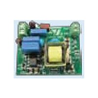
EVAL BOARD FOR VIPER27
Manufacturer
STMicroelectronics
Series
VIPer™ plusr
Datasheet
1.VIPER27LD.pdf
(31 pages)
Specifications of EVLVIP27-7WLED
Features
3.5 ~ 7 W
Utilized Ic / Part
VIPer27
Maximum Operating Temperature
+ 150 C
Output Power
3.5 W to 7 W
Product
Power Management Development Tools
Supply Current
25 mA
Lead Free Status / RoHS Status
Lead free / RoHS Compliant
Voltage - Output
-
Voltage - Input
-
Current - Output / Channel
-
Outputs And Type
-
Lead Free Status / Rohs Status
Lead free / RoHS Compliant
For Use With/related Products
VIPer27
Other names
497-10607


Pin settings
3
Note:
4/31
Pin settings
Figure 3.
The copper area for heat dissipation has to be designed under the DRAIN pins.
Table 3.
DIP7
7,8
1
2
3
4
5
-
Pin n.
SO16N
13...16 DRAIN
1...2
4
5
6
7
8
Connection diagram (top view)
Pin description
CONT
Name
GND
VDD
N.A.
BR
FB
This pin represents the device ground and the source of the power
section.
Not available for user. It can be connected to GND (pins 1-2) or left not
connected.
Supply voltage of the control section. This pin also provides the charging
current of the external capacitor during start-up time.
Control pin. The following functions can be selected:
1. current limit set point adjustment. The internal set default value of the
cycle-by-cycle current limit can be reduced by connecting to ground an
external resistor.
2. output voltage monitoring. A voltage exceeding V
Table 8 on page 7
This function is strobed and digitally filtered for high noise immunity.
Control input for duty cycle control. Internal current generator provides
bias current for loop regulation. A voltage below the threshold V
activates the burst-mode operation. A level close to the threshold V
means that we are approaching the cycle-by-cycle over-current set point.
Brownout protection input with hysteresis. A voltage below the threshold
V
consumption. Device operation restarts as the voltage exceeds the
threshold V
High voltage drain pin. The built-in high voltage switched start-up bias
current is drawn from this pin too.
Pins connected to the metal frame to facilitate heat dissipation.
BRth
shuts down (not latch) the device and lowers the power
Doc ID 15133 Rev 5
BRth
+ V
) shuts the IC down reducing the device consumption.
BRhyst
. It can be connected to ground when not used.
Function
OVP
threshold (see
FBbm
VIPER27
FBlin
Related parts for EVLVIP27-7WLED
Image
Part Number
Description
Manufacturer
Datasheet
Request
R

Part Number:
Description:
STMicroelectronics [RIPPLE-CARRY BINARY COUNTER/DIVIDERS]
Manufacturer:
STMicroelectronics
Datasheet:
Part Number:
Description:
STMicroelectronics [LIQUID-CRYSTAL DISPLAY DRIVERS]
Manufacturer:
STMicroelectronics
Datasheet:

Part Number:
Description:
BOARD EVAL FOR MEMS SENSORS
Manufacturer:
STMicroelectronics
Datasheet:
Part Number:
Description:
NPN TRANSISTOR POWER MODULE
Manufacturer:
STMicroelectronics
Datasheet:
Part Number:
Description:
TURBOSWITCH ULTRA-FAST HIGH VOLTAGE DIODE
Manufacturer:
STMicroelectronics
Datasheet:
Part Number:
Description:
Manufacturer:
STMicroelectronics
Datasheet:
Part Number:
Description:
DIODE / SCR MODULE
Manufacturer:
STMicroelectronics
Datasheet:
Part Number:
Description:
DIODE / SCR MODULE
Manufacturer:
STMicroelectronics
Datasheet:
Part Number:
Description:
Search -----> STE16N100
Manufacturer:
STMicroelectronics
Datasheet:
Part Number:
Description:
Search ---> STE53NA50
Manufacturer:
STMicroelectronics
Datasheet:
Part Number:
Description:
NPN Transistor Power Module
Manufacturer:
STMicroelectronics
Datasheet:
Part Number:
Description:
DIODE / SCR MODULE
Manufacturer:
STMicroelectronics
Datasheet: