STEVAL-ILL027V1 STMicroelectronics, STEVAL-ILL027V1 Datasheet - Page 16
STEVAL-ILL027V1
Manufacturer Part Number
STEVAL-ILL027V1
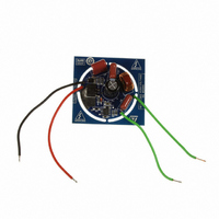
Description
BOARD EVAL LED DRIVER FOR L6562A
Manufacturer
STMicroelectronics
Datasheets
1.L6562ADTR.pdf
(26 pages)
2.STEVAL-ILL027V1.pdf
(4 pages)
3.STEVAL-ILL027V1.pdf
(23 pages)
Specifications of STEVAL-ILL027V1
Design Resources
STEVAL-ILL027V1 Schematics STEVAL-ILL027V1 BOM STEVAL-ILL027V1 Gerber Files
Current - Output / Channel
260mA
Outputs And Type
1, Non-Isolated
Voltage - Output
70V
Features
Short-Circuit Protection
Voltage - Input
120VAC
Utilized Ic / Part
L6562A
Product
Display Modules
Lead Free Status / RoHS Status
Lead free by exemption / RoHS compliant by exemption
Other names
497-10170


Application information
7.4
16/26
Operating with no auxiliary winding on the boost inductor
To generate the synchronization signal on the ZCD pin, the typical approach requires the
connection between the pin and an auxiliary winding of the boost inductor through a limiting
resistor. When the device is supplied by the cascaded DC-DC converter, it is necessary to
introduce a supplementary winding to the PFC choke just to operate the ZCD pin.
Another solution could be implemented by simply connecting the ZCD pin to the drain of the
power MOSFET through an R-C network as shown in figure 3: in this way the high-
frequency edges experienced by the drain will be transferred to the ZCD pin, hence arming
and triggering the ZCD comparator.
Also in this case the resistance value must be properly chosen to limit the current
sourced/sunk by the ZCD pin. In typical applications with output voltages around 400V,
recommended values for these components are 22pF (or 33pF) for C
R
between the regulated output voltage and the peak input voltage
Figure 20. ZCD pin synchronization without auxiliary winding
ZCD
. With these values proper operation is guaranteed even with few volts difference
ZCD
L6562A
5
R
ZCD
C
ZCD
ZCD
and 330k for
L6562A
Related parts for STEVAL-ILL027V1
Image
Part Number
Description
Manufacturer
Datasheet
Request
R

Part Number:
Description:
BOARD EVAL FOR MEMS SENSORS
Manufacturer:
STMicroelectronics
Datasheet:

Part Number:
Description:
KIT DEV STARTER ST10F276Z5
Manufacturer:
STMicroelectronics
Datasheet:

Part Number:
Description:
BOARD EVAL HDMI $ VIDEO SWITCH
Manufacturer:
STMicroelectronics
Datasheet:

Part Number:
Description:
BOARD DEMO ACCELEROMETER DIL24
Manufacturer:
STMicroelectronics
Datasheet:

Part Number:
Description:
BOARD STLM75/STDS75/ST72F651
Manufacturer:
STMicroelectronics
Datasheet:

Part Number:
Description:
EVAL BOARD 3AXIS MEMS ACCELLRMTR
Manufacturer:
STMicroelectronics
Datasheet:

Part Number:
Description:
BOARD EVAL 8BIT MICRO + TDE1708
Manufacturer:
STMicroelectronics
Datasheet:

Part Number:
Description:
EVAL BOARD A/D TS4657
Manufacturer:
STMicroelectronics
Datasheet:

Part Number:
Description:
BOARD ADAPTER 20DIP LIS3LV02DL
Manufacturer:
STMicroelectronics
Datasheet:

Part Number:
Description:
BOARD DEMO STM8S207R6/LIS331DLH
Manufacturer:
STMicroelectronics
Datasheet:

Part Number:
Description:
STMicroelectronics [RIPPLE-CARRY BINARY COUNTER/DIVIDERS]
Manufacturer:
STMicroelectronics
Datasheet:
Part Number:
Description:
STMicroelectronics [LIQUID-CRYSTAL DISPLAY DRIVERS]
Manufacturer:
STMicroelectronics
Datasheet:
Part Number:
Description:
BOARD EVAL FOR MEMS SENSORS
Manufacturer:
STMicroelectronics
Datasheet: