STEVAL-ILL008V1 STMicroelectronics, STEVAL-ILL008V1 Datasheet - Page 2
STEVAL-ILL008V1
Manufacturer Part Number
STEVAL-ILL008V1
Description
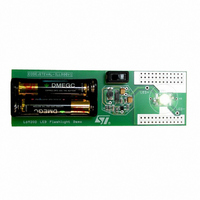
EVAL BOARD CREE LED FLASHLIGHT
Manufacturer
STMicroelectronics
Datasheets
1.L6920DC.pdf
(13 pages)
2.STEVAL-ILL008V1.pdf
(4 pages)
3.STEVAL-ILL008V1.pdf
(15 pages)
Specifications of STEVAL-ILL008V1
Mfg Application Notes
Low Voltage LED Driver AppNote
Design Resources
STEVAL-ILL008V1 Gerber Files STEVAL-ILL008V1 Schematic STEVAL-ILL008V1 Bill of Materials
Outputs And Type
1, Non-Isolated
Voltage - Output
3.5V
Features
1V Start up Input Voltage
Voltage - Input
1 ~ 5.5 V
Utilized Ic / Part
L6920
Product
Display Modules
Core Chip
L6920DA
Output Voltage
3.5V
Kit Contents
L6920D, L4971, L6902D Reference Board
Development Tool Type
Hardware - Eval/Demo Board
Tool / Board Applications
LED Flashlight
Mcu Supported Families
L6920DA
Lead Free Status / RoHS Status
Lead free / RoHS Compliant
Current - Output / Channel
-
Lead Free Status / Rohs Status
Details
Other names
497-5516


AN1941 APPLICATION NOTE
2 L6920D LED DRIVER
White LEDs are gaining popularity as sources of illumination because of their high efficiency
and reliability. Typical forward voltage drop of a white LED is approximately 3.5V. When these
LEDs are powered from a single or two cell batteries, a boost converter is needed to boost the
voltage to drive the LEDs.
2.1 L6920D Description
L6920D is a high efficiency step-up converter requiring very few external components to real-
ize the conversion from the battery voltage to the selected output voltage or current. The start-
up is guaranteed at 1V and the device is operating down to 0.6V. The device has very low qui-
escent current, only 10 A. Internal synchronous rectifier is implemented with a 120m
channel MOSFET, replacing the conventional boost diode, to improve the efficiency. This also
implies a reduced cost in the application since no external diode required.
Following is the block diagram of L6920D.
Figure 2. Block diagram of L6920D
In L6920D, the control is based on the comparator that continuously checks the status of the
feedback signal. If the feedback voltage is lower than reference value, the control function of
the L6920D directs the energy stored in the inductor to be transferred to the load. This is ac-
complished by alternating between two basic steps:
2/15
– Ton phase: the bottom MOFSET Q1 is turned on, and the inductor is charged. The switch
– Toff phase: the bottom MOSFET Q1 is turned off, and top MOSFET Q2 is turned on. The
SHDN
V
is turned off if the current reaches 1A or after a maximum on-time set to 5s.
energy stored in the inductor is transferred to the load for at least a minimum off time of
1s. After this, the synchronous switch is turned off as soon as the feedback signal goes
lower than reference or the current flowing in the inductor goes down to zero.
LBO
REF
A
B
C
-
+
-
+
Y
VBG
V
GND
R
Toff min
FB
1 sec
OUT
VBG
1
VBG
,R
+
-
2
OPAMP
LBI
Y
A
B
C
(CR)
Q
S
ZERO CROSSING
R
Ton max
5 sec
-
+
CURRENT LIMIT
- +
-
+
VOUT
D99IN1041
OUT
LX
GND
FB
V
IN
V
OUT
P-
Related parts for STEVAL-ILL008V1
Image
Part Number
Description
Manufacturer
Datasheet
Request
R

Part Number:
Description:
BOARD EVAL FOR MEMS SENSORS
Manufacturer:
STMicroelectronics
Datasheet:

Part Number:
Description:
KIT DEV STARTER ST10F276Z5
Manufacturer:
STMicroelectronics
Datasheet:

Part Number:
Description:
BOARD EVAL HDMI $ VIDEO SWITCH
Manufacturer:
STMicroelectronics
Datasheet:

Part Number:
Description:
BOARD DEMO ACCELEROMETER DIL24
Manufacturer:
STMicroelectronics
Datasheet:

Part Number:
Description:
BOARD STLM75/STDS75/ST72F651
Manufacturer:
STMicroelectronics
Datasheet:

Part Number:
Description:
EVAL BOARD 3AXIS MEMS ACCELLRMTR
Manufacturer:
STMicroelectronics
Datasheet:

Part Number:
Description:
BOARD EVAL 8BIT MICRO + TDE1708
Manufacturer:
STMicroelectronics
Datasheet:

Part Number:
Description:
EVAL BOARD A/D TS4657
Manufacturer:
STMicroelectronics
Datasheet:

Part Number:
Description:
BOARD ADAPTER 20DIP LIS3LV02DL
Manufacturer:
STMicroelectronics
Datasheet:

Part Number:
Description:
BOARD DEMO STM8S207R6/LIS331DLH
Manufacturer:
STMicroelectronics
Datasheet:

Part Number:
Description:
STMicroelectronics [RIPPLE-CARRY BINARY COUNTER/DIVIDERS]
Manufacturer:
STMicroelectronics
Datasheet:
Part Number:
Description:
STMicroelectronics [LIQUID-CRYSTAL DISPLAY DRIVERS]
Manufacturer:
STMicroelectronics
Datasheet:
Part Number:
Description:
BOARD EVAL FOR MEMS SENSORS
Manufacturer:
STMicroelectronics
Datasheet: