LM3503ITL-25EV National Semiconductor, LM3503ITL-25EV Datasheet - Page 14
LM3503ITL-25EV
Manufacturer Part Number
LM3503ITL-25EV
Description
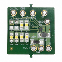
BOARD EVALUATION LM3503ITL-25
Manufacturer
National Semiconductor
Series
PowerWise®r
Specifications of LM3503ITL-25EV
Current - Output / Channel
9mA
Outputs And Type
2, Non-Isolated
Voltage - Output
25 V
Features
Dual Display(s)
Voltage - Input
2.7 ~ 5.5V
Utilized Ic / Part
LM3503
Core Chip
LM3503
Topology
Boost
No. Of Outputs
1
Output Voltage
25V
Input Voltage
2.5V To 5.5V
Development Tool Type
Hardware - Eval/Demo Board
Lead Free Status / RoHS Status
Not applicable / Not applicable


www.national.com
Application Information
WHITE LED CURRENT SETTING
The white LED current is controlled by a DC voltage at the
Cntrl pin.
The relationship between the Cntrl pin voltage and Fb pin
voltage can be computed with the following:
V
V
Aside from varying the DC voltage at the Cntrl pin, white LED
dimming can be accomplished through the RC filtering of a
PWM signal. The PWM signal frequency should be at least a
decade greater than the RC filter bandwidth. Figure 3 is how
the LM3503 should be wired for PWM filtered white LED
dimming functionality. When using PWM dimming, it is rec-
ommended to add 1-2ms delay between the Cntrl signal and
the main Enable sginal (En1) to allow time for the output to
discharge. This will prevent potential flickering especially if
the Sub display is compose of 2 LEDs or less.
The equations below are guidelines for choosing the correct
RC filter values in relation to the PWM signal frequency.
Equation #1:
Cntrl
Fb
:
: Cntrl Pin Voltage. Voltage Range: 0.2V ≤ V
3.5V.
Feedback Pin Voltage.
FIGURE 3. If V
OUT2
WHITE LED DIMMING
Cntrl
is not used, En2 must be grounded
≤
14
LED CURRENT
The LED current is set using the following equation:
To determine the maximum output current capability of the
device, it is best to estimate using equations on page 16 and
the minimum peak current limit of the device (see electrical
table). Note the current capability will be higher with less
LEDs in the application.
Equation #2:
F
F
R:
C:
For example, using the above equations to determine the
proper RC values. Assume the following condition:V
C=0.01µF and F
equation 2. By rearranging equation 1 to solve for R; R =
318.5K ohms (standard value, R = 316K).
RC
PWM
:
: PWM Signal Frequency.
RC Filter Bandwidth Cutoff Frequency.
Chosen Filter Resistor.
Chosen Filter Capacitor.
PWM
= 500Hz, then F
20128634
RC
= 50Hz by relation to
IN
= 3.6V,
Related parts for LM3503ITL-25EV
Image
Part Number
Description
Manufacturer
Datasheet
Request
R

Part Number:
Description:
IC LED DRVR WHT BCKLT 10MICROSMD
Manufacturer:
National Semiconductor
Datasheet:
Part Number:
Description:
IC LED DRVR WHT BCKLT 10MICROSMD
Manufacturer:
National Semiconductor
Datasheet:
Part Number:
Description:
IC LED DRVR WHT BCKLT 10MICROSMD
Manufacturer:
National Semiconductor
Datasheet:
Part Number:
Description:
IC LED DRVR WHT BCKLT 10MICROSMD
Manufacturer:
National Semiconductor
Datasheet:

Part Number:
Description:
IC, LED DRIVER, CONSTANT CURRENT, µSMD16
Manufacturer:
National Semiconductor
Datasheet:

Part Number:
Description:
Dual-Display Constant Current LED Driver with Analog Brightness Control
Manufacturer:
National Semiconductor
Datasheet:
Part Number:
Description:
LM3503 Dual-Display Constant Current LED Driver with Analog Brightness Control; Package: MICRO SMD; No of Pins: 10; Qty per Container: 250; Container: Reel
Manufacturer:
National Semiconductor
Datasheet:
Part Number:
Description:
National Semiconductor [8-Bit D/A Converter]
Manufacturer:
National Semiconductor
Datasheet:
Part Number:
Description:
National Semiconductor [Media Coprocessor]
Manufacturer:
National Semiconductor
Datasheet:
Part Number:
Description:
Digitally Controlled Tone and Volume Circuit with Stereo Audio Power Amplifier, Microphone Preamp Stage and National 3D Sound
Manufacturer:
National Semiconductor
Datasheet:
Part Number:
Description:
Digitally Controlled Tone and Volume Circuit with Stereo Audio Power Amplifier, Microphone Preamp Stage and National 3D Sound
Manufacturer:
National Semiconductor
Datasheet:
Part Number:
Description:
AC97 Rev 2 Codec with Sample Rate Conversion and National 3D Sound
Manufacturer:
National Semiconductor
Part Number:
Description:
Manufacturer:
National Semiconductor
Datasheet:
Part Number:
Description:
Manufacturer:
National Semiconductor
Datasheet: