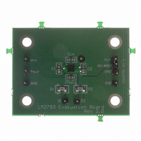
LM2793LDEV National Semiconductor, LM2793LDEV Datasheet - Page 7

LM2793LDEV
Manufacturer Part Number
LM2793LDEV
Description
BOARD EVALUATION LM2793LD
Manufacturer
National Semiconductor
Series
PowerWise®r
Specifications of LM2793LDEV
Current - Output / Channel
16mA
Outputs And Type
2, Non-Isolated
Voltage - Output
4 V
Features
Charge Pump
Voltage - Input
2.7 ~ 5.5V
Utilized Ic / Part
LM2793
Lead Free Status / RoHS Status
Not applicable / Not applicable
Application Information
CIRCUIT DESCRIPTION
The LM2793 is a 1.5x CMOS charge pump that provides two
matched constant current outputs for driving up to 16mA
through high forward voltage drop White LEDs from Li-Ion
battery sources. The device has two regulated current
sources connected to the output of the device’s 1.5x loosely
regulated charge pump (P
regulated charge pump has both open loop and closed loop
modes of operation. When the device is in open loop, the
voltage at P
the device is in closed loop, the voltage at P
regulated to 4.9V (typ.). To set the LED drive current, the
device uses the voltage applied to the dual function
shutdown-brightness pin (SD-BRGT) to set a reference cur-
rent. This reference current is then multiplied and mirrored to
each current output. The LED brightness can be controlled
by both analog and/or digital methods. The digital technique
uses a PWM (Pulse Width Modulation) signal applied to the
SD-BRGT pin. The analog technique applies an analog volt-
age in the range of 0.7V to 2.75 to the SD-BRGT pin to vary
the LED current (see Shutdown and Brightness Control).
SOFT START
LM2793 includes a soft start function to reduce the inrush
currents and high peak current during power up of the de-
vice. Soft start is implemented internally by ramping the
reference voltage more slowly than the applied voltage.
During soft start, the switch resistances limit the inrush cur-
rent used to charge the flying and hold capacitors.
SHUTDOWN AND BRIGHTNESS CONTROL
The LM2793 has an active-low dual function shutdown-
brightness control pin, SD-BRGT. A voltage higher than
0.65V (typ.) on SD-BRGT will put the LM2793 in active
mode. Applying a voltage below 0.35V (typ.) on the SD-
BRGT pin will turn off the device, reducing the quiescent
current to 3µA (typ.).
The LM2793 has the ability to adjust LED brightness by
applying an analog voltage or a PWM signal to the SD-
BRGT pin. For constant brightness or analog brightness
control, continue with “Analog brightness control” below.
Otherwise go to “Brightness control using PWM”.
1. Analog brightness control
2. Brightness control using PWM
The current for the dual LED outputs can be adjusted by
varying the voltage on the SD-BRGT pin. The typical
range for adjusting LED brightness is between 0.7 and
2.75V. Figure 1 shows how the current changes with
respect to the voltage applied to SD-BRGT. If full bright-
ness (16mA) is desired, the voltage on SD-BRGT should
be greater than 2.75V (typ.) but not more than V
Increasing and decreasing the duty cycle of the PWM
signal controls the LED brightness. Zero duty cycle will
turn off the LEDs and a 50% duty cycle will result in an
average I
The recommended frequency range for the PWM signal
is between 100Hz and 1KHz. If the PWM frequency is
much less than 100Hz, flicker may be seen in the LEDs.
If the frequency is much higher than 1kHz, brightness in
the LEDs will not adjust linearly with duty cycle due to
the 30µs (typ.) start-up time of the device. The voltage
level for the PWM signal should be greater than 2.75V
(typ.) but not exceed the voltage on V
OUT
LED
is 1.5 times the voltage at the input. When
being half of the maximum LED current.
OUT
). The device’s loosely-
IN
.
OUT
is loosely
IN
.
7
CAPACITOR SELECTION
The LM2793 requires 4 external capacitors for proper opera-
tion. Surface-mount multi-layer ceramic capacitors are rec-
ommended. These capacitors are small, inexpensive and
have very low equivalent series resistance (ESR, ≤15mΩ
typ.). Tantalum capacitors, OS-CON capacitors, and alumi-
num electrolytic capacitors are generally not recommended
for use with the LM2793 due to their high ESR, as compared
to ceramic capacitors.
For most applications, ceramic capacitors with X7R or X5R
temperature characteristic are preferred for use with the
LM2793. These capacitors have tight capacitance tolerance
(as good as
85˚C), and typically have little voltage coefficient. Capacitors
with Y5V or Z5U temperature characteristic are generally not
recommended for use with the LM2793. Capacitors with
these temperature characteristics typically have wide ca-
pacitance tolerance (+80%, −20%), vary significantly over
temperature (Y5V: +22%, −82% over −30˚C to +85˚C range;
Z5U: +22%, −56% over +10˚C to +85˚C range), and have
poor voltage coefficients. Under some conditions, a nominal
1µF Y5V or Z5U capacitor could have a capacitance of only
0.1µF. Such detrimental deviation is likely to cause Y5V and
Z5U capacitors to fail to meet the minimum capacitance
requirements of the LM2793. Table 1 lists suggested capaci-
tor suppliers for the typical application circuit.
LED SELECTION
The LM2793 is designed to drive LEDs with a forward volt-
age of about 3.0V to 4.0V. The typical and maximum diode
forward voltage depends highly on the manufacturer and
their technology. Table 2 lists two suggested manufacturers.
Forward current matching is assured over the LED process
variations due to the constant current output of the LM2793.
±
15% over −55˚C to 125˚C; X5R:
Manufacturer
TABLE 1. Ceramic Capacitor Manufacturers
Taiyo Yuden
Murata
FIGURE 1. LED Current vs. V
TDK
±
2 LEDs, V
10%), hold their value over temperature (X7R:
DX
= 3.6V, V
www.component.tdk.com
www.t-yuden.com
www.murata.com
IN
Contact
±
15% over −55˚C to
= 3.6V
SD-BRGT
20063607
www.national.com


