LM3404EVAL/NOPB National Semiconductor, LM3404EVAL/NOPB Datasheet - Page 24
LM3404EVAL/NOPB
Manufacturer Part Number
LM3404EVAL/NOPB
Description
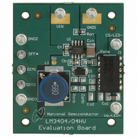
BOARD EVALUATION LM3404
Manufacturer
National Semiconductor
Series
PowerWise®r
Specifications of LM3404EVAL/NOPB
Current - Output / Channel
1A
Outputs And Type
1, Non-Isolated
Voltage - Output
4 V
Features
Dimmable
Voltage - Input
6 ~ 42 V
Utilized Ic / Part
LM3404
Silicon Manufacturer
National
Silicon Core Number
LM3404
Kit Application Type
Power Management - Voltage Regulator
Application Sub Type
Buck Regulator
Kit Contents
Board, User Guide, LM3404 Datasheet
Lead Free Status / RoHS Status
Lead free / RoHS Compliant
Other names
*LM3404EVAL
LM3404EVAL
LM3404EVAL
Available stocks
Company
Part Number
Manufacturer
Quantity
Price
Company:

Part Number:
LM3404EVAL/NOPB
Manufacturer:
National Semiconductor
Quantity:
135


www.national.com
C
The bootstrap capacitor C
capacitor with X7R dielectric. A 25V rating is appropriate for
all application circuits. The linear regulator filter capacitor C
should always be a 100 nF ceramic capacitor, also with X7R
dielectric and a 25V rating.
EFFICIENCY
To estimate the electrical efficiency of this example the power
dissipation in each current carrying element can be calculated
and summed. Electrical efficiency, η, should not be confused
with the optical efficacy of the circuit, which depends upon the
LEDs themselves.
Total output power, P
Conduction loss, P
Gate charging and VCC loss, P
regulator:
Switching loss, P
AC rms current loss, P
The dark grey, inner loop represents the high current path
during the MOSFET on-time. The light grey, outer loop rep-
resents the high current path during the off-time.
GROUND PLANE AND SHAPE ROUTING
The diagram of
of continuous current vs. the flow of pulsating currents. The
circuit paths with current flow during both the on-time and off-
time are considered to be continuous current, while those that
carry current during the on-time or off-time only are pulsating
currents. Preference in routing should be given to the pulsat-
B
P
P
AND C
P
G
C
S
= (600 x 10
= 0.5 x 48 x 0.5 x 40 x 10
= (I
F
F
2
x R
P
P
O
S
Figure 14
P
DSON
= I
= 0.5 x V
S
G
-6
, in the internal MOSFET:
C
F
= (I
+ 2.23 x 10
, in the internal MOSFET:
) x D = (0.5
x V
O
IN-OP
CIN
, is calculated as:
O
B
, in the input capacitor:
IN
is also useful for analyzing the flow
= 0.5 x 35.2 = 17.6W
should always be a 10 nF ceramic
+ f
x I
SW
F
5
G
2
x (t
-9
, in the gate drive and linear
x 6 x 10
x 0.8) x 0.73 = 146 mW
x Q
x 2.23 x 10
R
+ t
G
) x V
F
-9
) x f
FIGURE 14. Buck Converter Current Loops
) x 48 = 94 mW
IN
SW
5
= 107 mW
F
24
DCR loss, P
Recirculating diode loss, P
Current Sense Resistor Loss, P
Electrical efficiency, η = P
17.6 / (17.6 + 0.644) = 96%
Temperature Rise in the LM3404HV IC is calculated as:
Layout Considerations
The performance of any switching converter depends as
much upon the layout of the PCB as the component selection.
The following guidelines will help the user design a circuit with
maximum rejection of outside EMI and minimum generation
of unwanted EMI.
COMPACT LAYOUT
Parasitic inductance can be reduced by keeping the power
path components close together and keeping the area of the
loops that high currents travel small. Short, thick traces or
copper pours (shapes) are best. In particular, the switch node
(where L1, D1, and the SW pin connect) should be just large
enough to connect all three components without excessive
heating from the current it carries. The LM3404/04HV oper-
ates in two distinct cycles whose high current paths are shown
in
ing current paths, as these are the portions of the circuit most
likely to emit EMI. The ground plane of a PCB is a conductor
and return path, and it is susceptible to noise injection just as
any other circuit path. The continuous current paths on the
ground net can be routed on the system ground plane with
less risk of injecting noise into other circuits. The path be-
tween the input source and the input capacitor and the path
between the recirculating diode and the LEDs/current sense
resistor are examples of continuous current paths. In contrast,
the path between the recirculating diode and the input capac-
itor carries a large pulsating current. This path should be
P
T
CIN
Figure
LM3404
= I
IN(rms)
= (P
14:
P
L
L
C
, in the inductor
= I
2
+ P
x ESR = 0.222
F
2
G
x DCR = 0.5
+ P
S
155 = 54°C
) x θ
O
D
/ (P
= 47 mW
JA
2
2
0.003 = 0.1 mW (negligible)
SNS
20205428
O
= (0.146 + 0.094 + 0.107) x
x 0.56 = 140 mW
+ Sum of all loss terms) =
= 110 mW
Related parts for LM3404EVAL/NOPB
Image
Part Number
Description
Manufacturer
Datasheet
Request
R

Part Number:
Description:
LM3404 BUILD IT BOARD
Manufacturer:
National Semiconductor
Part Number:
Description:
LM3404 EVAL BOARD
Manufacturer:
National Semiconductor
Part Number:
Description:
National Semiconductor [8-Bit D/A Converter]
Manufacturer:
National Semiconductor
Datasheet:
Part Number:
Description:
National Semiconductor [Media Coprocessor]
Manufacturer:
National Semiconductor
Datasheet:
Part Number:
Description:
Digitally Controlled Tone and Volume Circuit with Stereo Audio Power Amplifier, Microphone Preamp Stage and National 3D Sound
Manufacturer:
National Semiconductor
Datasheet:
Part Number:
Description:
Digitally Controlled Tone and Volume Circuit with Stereo Audio Power Amplifier, Microphone Preamp Stage and National 3D Sound
Manufacturer:
National Semiconductor
Datasheet:
Part Number:
Description:
AC97 Rev 2 Codec with Sample Rate Conversion and National 3D Sound
Manufacturer:
National Semiconductor
Part Number:
Description:
Manufacturer:
National Semiconductor
Datasheet:
Part Number:
Description:
Manufacturer:
National Semiconductor
Datasheet:
Part Number:
Description:
General Purpose, Low Voltage, Low Power, Rail-to-Rail Output Operational Amplifiers
Manufacturer:
National Semiconductor
Datasheet:
Part Number:
Description:
8-bit 20 MSPS flash A/D converter.
Manufacturer:
National Semiconductor
Datasheet:
Part Number:
Description:
Low Noise Quad Operational Amplifier
Manufacturer:
National Semiconductor
Datasheet:
Part Number:
Description:
Quad Differential Line Receivers
Manufacturer:
National Semiconductor
Datasheet:
Part Number:
Description:
Quad High Speed Trapezoidal? Bus Transceiver
Manufacturer:
National Semiconductor
Datasheet: