LM3404EVAL/NOPB National Semiconductor, LM3404EVAL/NOPB Datasheet - Page 20
LM3404EVAL/NOPB
Manufacturer Part Number
LM3404EVAL/NOPB
Description
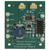
BOARD EVALUATION LM3404
Manufacturer
National Semiconductor
Series
PowerWise®r
Specifications of LM3404EVAL/NOPB
Current - Output / Channel
1A
Outputs And Type
1, Non-Isolated
Voltage - Output
4 V
Features
Dimmable
Voltage - Input
6 ~ 42 V
Utilized Ic / Part
LM3404
Silicon Manufacturer
National
Silicon Core Number
LM3404
Kit Application Type
Power Management - Voltage Regulator
Application Sub Type
Buck Regulator
Kit Contents
Board, User Guide, LM3404 Datasheet
Lead Free Status / RoHS Status
Lead free / RoHS Compliant
Other names
*LM3404EVAL
LM3404EVAL
LM3404EVAL
Available stocks
Company
Part Number
Manufacturer
Quantity
Price
Company:

Part Number:
LM3404EVAL/NOPB
Manufacturer:
National Semiconductor
Quantity:
135


www.national.com
R
A moderate switching frequency is needed in this application
to balance the requirements of magnetics size and efficiency.
R
follows:
The closest 1% tolerance resistor is 133 kΩ. The switching
frequency and on-time of the circuit can then be found using
the equations relating R
OUTPUT INDUCTOR
Since an output capacitor will be used to filter some of the AC
ripple current, the inductor ripple current can be set higher
than the LED ripple current. A value of 40%
many buck converters:
With the target ripple current determined the inductance can
be chosen:
The closest standard inductor value is 47 µH. The average
current rating should be greater than 700 mA to prevent over-
heating in the inductor. Separation between the LM3404
drivers and the LED arrays means that heat from the inductor
will not threaten the lifetime of the LEDs, but an overheated
inductor could still cause the LM3404 to enter thermal shut-
down.
The inductance of the standard part chosen is ±20%. With this
tolerance the typical, minimum, and maximum inductor cur-
rent ripples can be calculated:
ON
ON
and t
is selected from the equation for switching frequency as
L
f
MIN
R
SW
t
Δi
ON
Δi
Δi
ON
L(MAX)
ON
L(TYP)
L(MIN)
= 7.1 / (1.33 x 10
= [(24 – 7.1) x 7.43 x 10
= (1.34 x 10
= 7.1 / (1.34 x 10
= [(24 - 7.1) x 7.43 x 10
= [(24 - 7.1) x 7.43 x 10
= [(24 - 7.1) x 7.43 x 10
Δi
L
= 0.4 x 0.7 = 0.28A
-10
ON
= 266 mA
= 223 mA
x 1.33 x 10
and t
5
-10
x 1.34 x 10
x 4 x 10
ON
P-P
P-P
-7
to f
] / (0.28) = 44.8 µH
5
SW
) / 24 = 743 ns
-7
-7
-7
5
-10
) = 132.5 kΩ
] / 47 x 10
] / 56 x 10
:
] / 38 x 10
) = 398 kHz
P-P
is typical in
-6
-6
-6
20
The peak LED/inductor current is then estimated:
In the case of a short circuit across the LED array, the LM3404
will continue to deliver rated current through the short but will
reduce the output voltage to equal the CS pin voltage of 200
mV. The inductor ripple current and peak current in this con-
dition would be equal to:
In the case of a short at the switch node, the output, or from
the CS pin to ground the short circuit current limit will engage
at a typical peak current of 1.5A. In order to prevent inductor
saturation during these fault conditions the inductor’s peak
current rating must be above 1.5A. A 47 µH off-the shelf in-
ductor rated to 1.4A (peak) and 1.5A (average) with a DCR of
0.1Ω will be used.
USING AN OUTPUT CAPACITOR
This application does not require high frequency PWM dim-
ming, allowing the use of an output capacitor to reduce the
size and cost of the output inductor. To select the proper out-
put capacitor the equation from Buck Regulators with Output
Capacitors is re-arranged to yield the following:
The target tolerance for LED ripple current is 100 mA
a typical value for r
LED datasheet. The required capacitor impedance to reduce
the worst-case inductor ripple current of 333 mA
fore:
A ceramic capacitor will be used and the required capacitance
is selected based on the impedance at 400 kHz:
This calculation assumes that impedance due to the equiva-
lent series resistance (ESR) and equivalent series inductance
(ESL) of C
value is 1.0 µF. The capacitor used should be rated to 25V or
more and have an X7R dielectric. Several manufacturers pro-
duce ceramic capacitors with these specifications in the 0805
case size. A typical value for ESR of 3 mΩ can be read from
the curve of impedance vs. frequency in the product
datasheet.
Δi
L(LED-SHORT)
C
O
O
Z
I
I
is negligible. The closest 10% tolerance capacitor
L(PEAK)
L(PEAK)
C
= 1/(2 x
= [0.1 / (0.333 - 0.1] x 1.8 = 0.77Ω
I
L(PEAK)
= [(24 – 0.2) x 7.43 x 10
D
= 0.7 + 0.5 x 0.330 = 866 mA
= 0.7 + 0.5 x 0.465 = 933 mA
of 1.8Ω at 700 mA can be read from the
π
= 330 mA
= 465 mA
x 0.77 x 4 x 10
= I
L
+ 0.5 x Δi
P-P
P-P
L(MAX)
5
) = 0.51 µF
-7
] / 38 x 10
P-P
is there-
P-P
-6
, and
Related parts for LM3404EVAL/NOPB
Image
Part Number
Description
Manufacturer
Datasheet
Request
R

Part Number:
Description:
LM3404 BUILD IT BOARD
Manufacturer:
National Semiconductor
Part Number:
Description:
LM3404 EVAL BOARD
Manufacturer:
National Semiconductor
Part Number:
Description:
National Semiconductor [8-Bit D/A Converter]
Manufacturer:
National Semiconductor
Datasheet:
Part Number:
Description:
National Semiconductor [Media Coprocessor]
Manufacturer:
National Semiconductor
Datasheet:
Part Number:
Description:
Digitally Controlled Tone and Volume Circuit with Stereo Audio Power Amplifier, Microphone Preamp Stage and National 3D Sound
Manufacturer:
National Semiconductor
Datasheet:
Part Number:
Description:
Digitally Controlled Tone and Volume Circuit with Stereo Audio Power Amplifier, Microphone Preamp Stage and National 3D Sound
Manufacturer:
National Semiconductor
Datasheet:
Part Number:
Description:
AC97 Rev 2 Codec with Sample Rate Conversion and National 3D Sound
Manufacturer:
National Semiconductor
Part Number:
Description:
Manufacturer:
National Semiconductor
Datasheet:
Part Number:
Description:
Manufacturer:
National Semiconductor
Datasheet:
Part Number:
Description:
General Purpose, Low Voltage, Low Power, Rail-to-Rail Output Operational Amplifiers
Manufacturer:
National Semiconductor
Datasheet:
Part Number:
Description:
8-bit 20 MSPS flash A/D converter.
Manufacturer:
National Semiconductor
Datasheet:
Part Number:
Description:
Low Noise Quad Operational Amplifier
Manufacturer:
National Semiconductor
Datasheet:
Part Number:
Description:
Quad Differential Line Receivers
Manufacturer:
National Semiconductor
Datasheet:
Part Number:
Description:
Quad High Speed Trapezoidal? Bus Transceiver
Manufacturer:
National Semiconductor
Datasheet: