LM3445-120VSMEV/NOPB National Semiconductor, LM3445-120VSMEV/NOPB Datasheet - Page 14
LM3445-120VSMEV/NOPB
Manufacturer Part Number
LM3445-120VSMEV/NOPB
Description
BOARD EVAL LM3445 110V
Manufacturer
National Semiconductor
Series
PowerWise®r
Specifications of LM3445-120VSMEV/NOPB
Current - Output / Channel
350mA
Outputs And Type
1, Non-Isolated
Features
Dimmable
Voltage - Input
90 ~ 135VAC
Utilized Ic / Part
LM3445
Core Chip
LM3445
Topology
Buck (Step Down)
No. Of Outputs
1
Dimming Control Type
Analog
Development Tool Type
Hardware - Eval/Demo Board
Mcu Supported Families
LM3445 Family
Msl
MSL 1 - Unlimited
Lead Free Status / RoHS Status
Lead free / RoHS Compliant
Voltage - Output
-
Lead Free Status / Rohs Status
Supplier Unconfirmed
Other names
LM3445-120VSMEV
Available stocks
Company
Part Number
Manufacturer
Quantity
Price
Company:

Part Number:
LM3445-120VSMEV/NOPB
Manufacturer:
National Semiconductor
Quantity:
135


www.national.com
MASTER/SLAVE OPERATION
Multiple LM3445s can be configured so that large strings of
LEDs can be controlled by a single triac dimmer. By doing so,
smooth consistent dimming for multiple LED circuits is
achieved.
When the FLTR1 pin is tied above 4.9V (typical), preferably
to VCC, the ramp comparator is tri-stated, disabling the dim
decoder. This allows one or more LM3445 devices or PWM
LED driver devices (slaves) to be controlled by a single
LM3445 (master) by connecting their DIM pins together.
MASTER/SLAVE CONFIGURATION
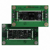
National Semiconductor offers an LM3445 demonstration
PCB for customer evaluation through our website. The fol-
lowing description and theory uses reference designators that
follow our evaluation PCB. The LM3445 Master/Slave
schematics are illustrated below (figures 13 - 15) for clarity.
Each board contains a separate circuit for the Master and
Slave function. Both the Master and Slave boards will need
to be modified from their original stand alone function so that
they can be coupled together. Only the Master LM3445 re-
quires use of the Master/Slave circuit for any number of
slaves.
14
MASTER BOARD MODIFICATIONS
•
•
•
SLAVE BOARD(S) MODIFICATIONS
•
•
MASTER/SLAVE(S) INTERCONNECTION
•
•
MASTER/SLAVE THEORY OF OPERATION
By placing two series diodes on the Master VCC circuit one
forces the master VCC UVLO to become the dominant thresh-
old. When Master VCC drops below UVLO, GATE stops
switching and the RC timer (>200 µs) rises above the TL431
threshold (2.5V) which in turn pulls down on the gate of the
Slave pass device (Q1).
The valley-fill circuit could consist of one large circuit to power
all LM3445 series connected, or each LM3445 circuit could
have a separate valley-fill circuit located near the buck con-
verter.
Remove R10 and replace with a BAS40 diode
Connect TP18 to TP14 (V
Connect TP17 (gate of Q5) to TP15 (gate of Q2)
Remove R11 (disconnects BLDR)
Tie TP14 (FLTR1) to V
Connect TP19 of Master to TP10 of Slave (Master VCC
Control)
Connect TP6 (DIM pin) of Master to TP6 (DIM pin) of Slave
(Master DIM Control)
CC
CC
)
Related parts for LM3445-120VSMEV/NOPB
Image
Part Number
Description
Manufacturer
Datasheet
Request
R

Part Number:
Description:
IC LED DRIVER TRIAC DIMM 10-MSOP
Manufacturer:
National Semiconductor
Datasheet:
Part Number:
Description:
IC LED DRIVER TRIAC DIMM 10-MSOP
Manufacturer:
National Semiconductor
Datasheet:

Part Number:
Description:
National Semiconductor [8-Bit D/A Converter]
Manufacturer:
National Semiconductor
Datasheet:
Part Number:
Description:
National Semiconductor [Media Coprocessor]
Manufacturer:
National Semiconductor
Datasheet:
Part Number:
Description:
Digitally Controlled Tone and Volume Circuit with Stereo Audio Power Amplifier, Microphone Preamp Stage and National 3D Sound
Manufacturer:
National Semiconductor
Datasheet:
Part Number:
Description:
Digitally Controlled Tone and Volume Circuit with Stereo Audio Power Amplifier, Microphone Preamp Stage and National 3D Sound
Manufacturer:
National Semiconductor
Datasheet:
Part Number:
Description:
AC97 Rev 2 Codec with Sample Rate Conversion and National 3D Sound
Manufacturer:
National Semiconductor
Part Number:
Description:
Manufacturer:
National Semiconductor
Datasheet:
Part Number:
Description:
Manufacturer:
National Semiconductor
Datasheet:
Part Number:
Description:
General Purpose, Low Voltage, Low Power, Rail-to-Rail Output Operational Amplifiers
Manufacturer:
National Semiconductor
Datasheet:
Part Number:
Description:
8-bit 20 MSPS flash A/D converter.
Manufacturer:
National Semiconductor
Datasheet:
Part Number:
Description:
Low Noise Quad Operational Amplifier
Manufacturer:
National Semiconductor
Datasheet:
Part Number:
Description:
Quad Differential Line Receivers
Manufacturer:
National Semiconductor
Datasheet:
Part Number:
Description:
Quad High Speed Trapezoidal? Bus Transceiver
Manufacturer:
National Semiconductor
Datasheet: