AD9717-EBZ Analog Devices Inc, AD9717-EBZ Datasheet - Page 44
AD9717-EBZ
Manufacturer Part Number
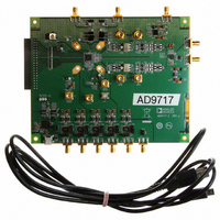
AD9717-EBZ
Description
BOARD EVAL FOR AD9717
Manufacturer
Analog Devices Inc
Series
TxDAC®r
Datasheet
1.AD9717BCPZ.pdf
(80 pages)
Specifications of AD9717-EBZ
Number Of Dac's
2
Number Of Bits
14
Outputs And Type
2, Differential
Sampling Rate (per Second)
125M
Data Interface
Serial
Dac Type
Current
Voltage Supply Source
Analog and Digital
Operating Temperature
-40°C ~ 85°C
Utilized Ic / Part
AD9717
Lead Free Status / RoHS Status
Lead free / RoHS Compliant


AD9714/AD9715/AD9716/AD9717
DAC TRANSFER FUNCTION
The AD9714/AD9715/AD9716/AD9717 provide two differen-
tial current outputs, IOUTP/IOUTN and QOUTP/QOUTN.
IOUTP and QOUTP provide a near full-scale current output,
I
where N = 8, 10, 12, or 14 for the AD9714, AD9715, AD9716,
and AD9717, respectively), while IOUTN and QOUTN, the
complementary outputs, provide no current. The current
outputs appearing at the positive DAC outputs, IOUTP and
QOUTP, and at the negative DAC outputs, IOUTN and QOUTN,
are a function of both the input code and I
expressed as follows:
where:
IDAC CODE and QDAC CODE = 0 to 2
representation).
I
and I
voltage, V
tively. I
where:
or
A differential pair (IOUTP/IOUTN or QOUTP/QOUTN)
typically drives a resistive load directly or via a transformer. If
dc coupling is required, the differential pair (IOUTP/IOUTN or
QOUTP/QOUTN) should be connected to matching resistive
loads, xR
single-ended voltage output appearing at the positive and
negative nodes is
To achieve the maximum output compliance of 1 V at the
nominal 4 mA output current, IR
to 250 Ω.
xOUTFS
IOUTFS
IOUTP = (IDAC CODE/2
QOUTP = (QDAC CODE/2
IOUTN = ((2
QOUTN = ((2
I
I
I
I
I
I
V
V
V
V
QREF
IOUTFS
QOUTFS
IREF
QREF
IOUTFS
QOUTFS
, when all bits are high (that is, DAC CODE = 2
and I
IOUTP
QOUTP
IOUTN
QOUTN
IOUTFS
, respectively, which are nominally set by a reference
= V
LOAD
= V
REFIO
= 32 × I
= 32 × V
= IOUTP × IR
QOUTFS
= 32 × I
= IOUTN × IR
= 32 × V
= QOUTP × QR
= QOUTN × QR
and I
REFIO
, that are tied to analog common, AVSS. The
REFIO
, and external resistors, IR
/IR
are functions of the reference currents, I
/QR
N
QOUTFS
N
IREF
QREF
− 1) − IDAC CODE)/2
REFIO
SET
− 1) − QDAC CODE)/2
REFIO
SET
/IR
can be expressed as follows:
/QR
LOAD
LOAD
SET
LOAD
LOAD
SET
N
) × I
N
LOAD
) × I
IOUTFS
QOUTFS
= QR
N
SET
− 1 (that is, decimal
N
xOUTFS
and QR
LOAD
× I
N
× I
IOUTFS
must be set
and can be
QOUTFS
SET
, respec-
N
− 1,
IREF
Rev. A | Page 44 of 80
(1)
(2)
(3)
(4)
(5)
(6)
(7)
Substituting the values of IOUTP, IOUTN, and I
be expressed as
Equation 8 highlights some of the advantages of operating the
AD9714/AD9715/AD9716/AD9717 differentially. First, the
differential operation helps cancel common-mode error sources
associated with IOUTP and IOUTN, such as noise, distortion,
and dc offsets. Second, the differential code-dependent current and
subsequent voltage, V
voltage output (that is, V
the signal power to the load. Note that the gain drift temperature
performance for a single-ended output (V
differential output (V
AD9717 can be enhanced by selecting temperature-tracking
resistors for xR
relationship, as shown in Equation 8.
ANALOG OUTPUT
The complementary current outputs in each DAC, IOUTP/
IOUTN and QOUTP/QOUTN, can be configured for single-
ended or differential operation. IOUTP/IOUTN and QOUTP/
QOUTN can be converted into complementary single-ended
voltage outputs, V
via a load resistor, xR
Function section by Equation 6 through Equation 8. The differen-
tial voltages, V
and V
voltage via a transformer or a differential amplifier configuration.
The ac performance of the AD9714/AD9715/AD9716/AD9717
is optimum and is specified using a differential transformer-
coupled output in which the voltage swing at IOUTP and IOUTN
is limited to ±0.5 V. The distortion and noise performance of
the AD9714/AD9715/AD9716/AD9717 can be enhanced when
it is configured for differential operation. The common-mode
error sources of both IOUTP/IOUTN and QOUTP/QOUTN
can be significantly reduced by the common-mode rejection
of a transformer or differential amplifier. These common-mode
error sources include even-order distortion products and noise.
The enhancement in distortion performance becomes more
significant as the frequency content of the reconstructed wave-
form increases and/or its amplitude increases. This is due to
the first-order cancellation of various dynamic common-mode
distortion mechanisms, digital feedthrough, and noise. Performing
a differential-to-single-ended conversion via a transformer also
provides the ability to deliver twice the reconstructed signal
power to the load (assuming no source termination). Because
the output currents of IOUTP/IOUTN and QOUTP/QOUTN
are complementary, they become additive when processed
differentially.
V
(32 × V
QOUTP
IDIFF
= {(2 × IDAC CODE – (2
and V
REFIO
IDIFF
LOAD
/IR
QOUTN
and V
IOUTP
SET
and xR
IDIFF
LOAD
) × IR
IDIFF
and V
, can also be converted to a single-ended
QDIFF
IOUTP
) of the AD9714/AD9715/AD9716/
, as described in the DAC Transfer
, is twice the value of the single-ended
SET
LOAD
, existing between V
IOUTN
because of their ratiometric
or V
, as well as V
IOUTN
N
− 1))/2
), thus providing twice
IOUTP
N
} ×
QOUTP
and V
IOUTP
xREF
, V
and V
and V
IOUTN
IDIFF
) or
QOUTN
can
IOUTN
(8)
,
Related parts for AD9717-EBZ
Image
Part Number
Description
Manufacturer
Datasheet
Request
R

Part Number:
Description:
Dual 14B, Low Power D-A Converter
Manufacturer:
Analog Devices Inc
Datasheet:

Part Number:
Description:
±1.7g Dual-Axis IMEMS Accelerometer Evaluation Board
Manufacturer:
Analog Devices Inc
Datasheet:
Part Number:
Description:
Inertial Sensor Evaluation System
Manufacturer:
Analog Devices Inc
Datasheet:
Part Number:
Description:
Manufacturer:
Analog Devices Inc
Datasheet:
Part Number:
Description:
Manufacturer:
Analog Devices Inc
Datasheet:
Part Number:
Description:
Manufacturer:
Analog Devices Inc
Datasheet:
Part Number:
Description:
Manufacturer:
Analog Devices Inc
Datasheet:
Part Number:
Description:
Manufacturer:
Analog Devices Inc
Datasheet:
Part Number:
Description:
Manufacturer:
Analog Devices Inc
Datasheet:
Part Number:
Description:
Manufacturer:
Analog Devices Inc
Datasheet:
Part Number:
Description:
Manufacturer:
Analog Devices Inc
Datasheet:
Part Number:
Description:
Manufacturer:
Analog Devices Inc
Datasheet:
Part Number:
Description:
Manufacturer:
Analog Devices Inc
Datasheet: