EVAL-AD5425EBZ Analog Devices Inc, EVAL-AD5425EBZ Datasheet - Page 16
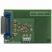
EVAL-AD5425EBZ
Manufacturer Part Number
EVAL-AD5425EBZ
Description
BOARD EVALUATION FOR AD5425
Manufacturer
Analog Devices Inc
Datasheet
1.AD5425YRMZ-REEL.pdf
(28 pages)
Specifications of EVAL-AD5425EBZ
Number Of Dac's
1
Number Of Bits
8
Outputs And Type
1, Differential
Sampling Rate (per Second)
2.47M
Data Interface
Serial
Settling Time
15ns
Dac Type
Current
Voltage Supply Source
Single
Operating Temperature
-40°C ~ 125°C
Utilized Ic / Part
AD5425
Lead Free Status / RoHS Status
Lead free / RoHS Compliant


AD5425
SINGLE-SUPPLY APPLICATIONS
Current Mode Operation
In the current mode circuit of Figure 32, I
is biased positive by an amount applied to V
configuration, the output voltage is given by
As D varies from 0 to 255, the output voltage varies from
V
sourcing all possible variations in current at the I
without any problems.
It is important to note that V
the switches in the DAC ladder no longer have the same source-
drain drive voltage. As a result, their on resistance differs and
this degrades the linearity of the DAC.
Voltage Switching Mode of Operation
Figure 33 shows this DAC operating in the voltage switching
mode. The reference voltage V
I
at the V
voltage results in a positive output voltage, making single-
supply operation possible. The output from the DAC is voltage
at a constant impedance (the DAC ladder resistance), thus an
op amp is necessary to buffer the output voltage. The reference
input no longer sees constant input impedance, but one that
varies with code. So, the voltage input should be driven from a
low impedance source.
OUT
BIAS
V
2 is connected to AGND, and the output voltage is available
IN
V
V
should be a low impedance source capable of sinking and
NOTES:
1. ADDITIONAL PINS OMITTED FOR CLARITY.
2. C1 PHASE COMPENSATION (1pF TO 2pF) MAY BE
OUT
OUT
REF
REQUIRED IF A1 IS A HIGH SPEED AMPLIFIER.
= [D × (R
= V
terminal. In this configuration, a positive reference
Figure 32. Single-Supply Current Mode Operation
V
REF
BIAS
to V
GND
V
V
FB
DD
DD
/R
OUT
V
DAC
BIAS
= 2V
R
) × (V
FB
IN
I
I
OUT
OUT
BIAS
IN
is limited to low voltages because
BIAS
1
2
is applied to the I
− V
− V
IN
C1
IN
)] + V
OUT
A1
A1
BIAS
2 and hence I
. In this
BIAS
OUT
OUT
2 terminal
V
1 pin,
OUT
OUT
Rev. A | Page 16 of 28
1
It is important to note that V
the switches in the DAC ladder no longer have the same source
drain drive voltage. As a result, their on resistance differs, which
degrades the linearity of the DAC.
V
internal diode turns on, exceeding the maximum ratings of the
device. In this type of application, the full range of the DAC
multiplying capability is lost.
POSITIVE OUTPUT VOLTAGE
Note that the output voltage polarity is opposite to the V
polarity for dc reference voltages. To achieve a positive voltage
output, an applied negative reference to the input of the DAC is
preferred over the output inversion through an inverting
amplifier because of the resistor tolerance errors. To generate a
negative reference, the reference can be level shifted by an
op amp such that the V
become the virtual ground and −2.5 V respectively, as shown
in Figure 34.
IN
V
IN
+5V
–5V
must also not go negative by more than 0.3 V, otherwise an
Figure 34. Positive Voltage Output with Minimum of Components
NOTES:
1. ADDITIONAL PINS OMITTED FOR CLARITY.
2. C1 PHASE COMPENSATION (1pF TO 2pF) MAY BE REQUIRED
IF A1 IS A HIGH SPEED AMPLIFIER.
V
Figure 33. Single-Supply Voltage Switching Mode Operation
OUT
ADR03
GND
NOTES:
1
2
ADDITIONAL PINS OMITTED FOR CLARITY.
C1 PHASE COMPENSATION (1pF TO 2pF) MAY BE REQUIRED,
IF A1 IS A HIGH SPEED AMPLIFIER.
–2.5V
V
I
I
IN
OUT
OUT
1
2
R
V
FB
REF
V
DD
V
GND
OUT
DD
GND
V
V
= 5V
DD
DD
and GND pins of the reference
IN
R
V
is limited to low voltage because
FB
REF
I
I
OUT
OUT
1
2
R1
C1
A1
R2
A1
V
OUT
= 0V TO +2.5V
V
OUT
REF
Related parts for EVAL-AD5425EBZ
Image
Part Number
Description
Manufacturer
Datasheet
Request
R


Part Number:
Description:
BOARD EVAL FOR SI270X-A
Manufacturer:
Silicon Laboratories Inc
Datasheet:

Part Number:
Description:
BUCK CONV REF DESIGN KIT IP1201
Manufacturer:
International Rectifier
Datasheet:
Part Number:
Description:
BOARD DEMO SYNC DUAL BUCK CNVTER
Manufacturer:
International Rectifier
Datasheet:
Part Number:
Description:
BOARD DEMO SYNC BUCK CONVETER
Manufacturer:
International Rectifier
Datasheet:

Part Number:
Description:
EVALBOARD/EB Omnidirectional microphone - Analog
Manufacturer:
Analog Devices
Datasheet:
Part Number:
Description:
EVALBOARD/EB Omnidirectional microphone - Analog
Manufacturer:
Analog Devices
Datasheet:


Part Number:
Description:
BOARD EVAL LED DRIVER LT3756
Manufacturer:
Linear Technology
Datasheet:

Part Number:
Description:
BOARD EVAL FOR AD7741/7742
Manufacturer:
Analog Devices Inc
Datasheet:

Part Number:
Description:
±1.7g Dual-Axis IMEMS Accelerometer Evaluation Board
Manufacturer:
Analog Devices Inc
Datasheet:

Part Number:
Description:
IC MULTIPLIER ANALOG 8-SOIC T/R
Manufacturer:
Analog Devices Inc
Datasheet:

Part Number:
Description:
IC ANALOG MULTIPLIER 8-DIP
Manufacturer:
Analog Devices Inc
Datasheet:
Part Number:
Description:
IC ANALOG MULTIPLIER 8-SOIC
Manufacturer:
Analog Devices Inc
Datasheet:
Part Number:
Description:
IC ANALOG MULTIPLIER 8-DIP
Manufacturer:
Analog Devices Inc
Datasheet: