CDB4353 Cirrus Logic Inc, CDB4353 Datasheet - Page 6
CDB4353
Manufacturer Part Number
CDB4353
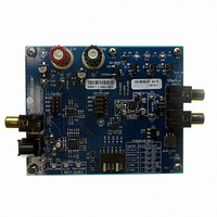
Description
BOARD EVAL FOR CS4353 DAC
Manufacturer
Cirrus Logic Inc
Specifications of CDB4353
Number Of Dac's
2
Number Of Bits
24
Outputs And Type
2, Single Ended
Sampling Rate (per Second)
192k
Data Interface
Serial
Dac Type
Voltage
Voltage Supply Source
Single
Operating Temperature
-40°C ~ 85°C
Utilized Ic / Part
CS4353
Silicon Manufacturer
Cirrus Logic
Application Sub Type
DAC
Kit Application Type
Data Converter
Silicon Core Number
CS4353
Kit Contents
Board
Lead Free Status / RoHS Status
Contains lead / RoHS non-compliant
Lead Free Status / RoHS Status
Contains lead / RoHS non-compliant
Other names
598-1519
CDB-4353
CDB-4353


6
10.BOARD CONNECTIONS AND SETTINGS
Board connections and settings are shown in
Note:
JUMPER
SWITCH
SPDIF INPUT - OPT1
EXT SYS CONN - J4
SPDIF INPUT - J16
J10
J11
S1
S2
PCM INPUT - J13
J1
J8
J9
J5
CONNECTOR
AOUTA - J14
AOUTB - J15
All settings denoted by an asterisk (*) are the Default Factory Settings.
3.3 V - J3
GND - J2
Resets CS4353 and CS8416
CS4353 De-emphasis select
Selects source of voltage for
CS8416 MCLK/LRCK Ratio
CS8416 and CS4353 PCM
CS4353 Output Reference
CS4353 Output Amplitude
Current measure for VCP
Current measure for VA
Selects PCM source for
Current measure for VL
CS4353 Reset Select
the VL supply
PURPOSE
PURPOSE
CS4353
Format
INPUT/OUTPUT
Output
Input
Input
Input
Input
Input
Input
Table 3. CDB4353 Jumper Settings
Table 4. CDB4353 Switch Settings
Table 2. System Connections
*EXTERNAL
POSITION
not shunted
not shunted
POSITION
Table
*shunted
*shunted
*shunted
*shunted
*shunted
Digital audio interface input via coaxial cable
+3.3 V power for the evaluation board
Ground connection from power supply
Digital audio interface input via optical cable
Input for master, serial, left/right clocks and serial data
Input for master, serial, left/right clocks and serial data - direct to CS4353
RCA line-level analog outputs
POR
1
2
3
4
5
-
2,
Table
3, and
When shunt is removed, the voltage can be measured
When shunt is removed, the voltage can be measured
When shunt is removed, the voltage can be measured
CS8416 must be reset if switch S1 position 2 or 3 is
across a fixed resistance to determine current.
across a fixed resistance to determine current.
across a fixed resistance to determine current.
Table 4
Voltage source is +3.3 V binding post (J3)
Output reference is J14 and J15 ground
CS4353 uses internal power-on reset
SIGNAL PRESENT
Output reference is board ground
Voltage source is pin 2 of J1
FUNCTION SELECTED
FUNCTION SELECTED
*down = MCLK is 256xFs
below.
*down = De-emphasis off
down = PCM Header J3
up = MCLK is 128xFs
up = De-emphasis on
down = 1 V
CS4353 reset by S2
*up = 2 V
*up = CS8416
*down = I
changed
up = LJ
rms
rms
output
2
output
S
CDB4353
DS803DB2
Related parts for CDB4353
Image
Part Number
Description
Manufacturer
Datasheet
Request
R

Part Number:
Description:
Development Kit
Manufacturer:
Cirrus Logic Inc
Datasheet:
Part Number:
Description:
Development Kit
Manufacturer:
Cirrus Logic Inc
Datasheet:


Part Number:
Description:
High-efficiency PFC + Fluorescent Lamp Driver Reference Design
Manufacturer:
Cirrus Logic Inc
Datasheet:
Part Number:
Description:
Development Kit
Manufacturer:
Cirrus Logic Inc
Datasheet:
Part Number:
Description:
Development Kit
Manufacturer:
Cirrus Logic Inc
Datasheet:

Part Number:
Description:
Development Kit
Manufacturer:
Cirrus Logic Inc
Datasheet:
Part Number:
Description:
Development Kit
Manufacturer:
Cirrus Logic Inc
Datasheet:
Part Number:
Description:
Development Kit
Manufacturer:
Cirrus Logic Inc
Datasheet:
Part Number:
Description:
Development Kit
Manufacturer:
Cirrus Logic Inc
Datasheet:

Part Number:
Description:
EVALUATION BOARD FOR CS8427
Manufacturer:
Cirrus Logic Inc
Datasheet:

Part Number:
Description:
BOARD EVAL FOR CS8416 RCVR
Manufacturer:
Cirrus Logic Inc
Datasheet:

Part Number:
Description:
EVALUATION BOARD FOR CS8420
Manufacturer:
Cirrus Logic Inc
Datasheet:

Part Number:
Description:
KIT DEVELOPMENT EP9315 ARM9
Manufacturer:
Cirrus Logic Inc
Datasheet:

Part Number:
Description:
KIT DEVELOPMENT EP9302 ARM9
Manufacturer:
Cirrus Logic Inc
Datasheet: