NCP1423EVB ON Semiconductor, NCP1423EVB Datasheet - Page 12
NCP1423EVB
Manufacturer Part Number
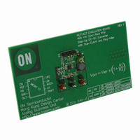
NCP1423EVB
Description
EVAL BOARD FOR NCP1423
Manufacturer
ON Semiconductor
Specifications of NCP1423EVB
Design Resources
NCP1423 Demo Board BOM NCP1423EVB Gerber Files NCP1423EVB Schematic
Main Purpose
DC/DC, Step Up
Outputs And Type
1, Non-Isolated
Voltage - Output
3.3V
Current - Output
400mA
Voltage - Input
2.5V
Regulator Topology
Boost
Frequency - Switching
600kHz
Board Type
Fully Populated
Utilized Ic / Part
NCP1423
Lead Free Status / RoHS Status
Lead free / RoHS Compliant
Power - Output
-
Lead Free Status / Rohs Status
Lead free / RoHS Compliant
For Use With/related Products
NCP1423
Other names
NCP1423EVBOS


General Design Procedures
choice an inductor and capacitor value can make the
converter has an optimum performance. Below a simple
method base on the most basic first order equations to
estimate the inductor and capacitor values for NCP1423
operate in Continuous Conduction Mode (CCM) is
introduced. The component value set can be used as a
starting point to fine−tune the circuit operation. By all
means, detail bench testing is needed to get the best
performance out of the circuit.
Design Parameters:
For one cells supply application
Calculate the feedback network:
Calculate the Low Battery Detect divider:
Switching mode converter design is important. Suitable
V
V
I
V
V
Select R2 = 100 k
V
Select R4 = 100 k
OUT
IN
OUT
LB
OUT−RIPPLE
LB0
R1 + R2
R1 + 100 k 3.3 V
R3 + R4
R3 + 100 k 1.0 V
= 1.1 V to 1.5 V, Typical 1.3 V
= 1.0 V
= 150 mA (200 mA max)
= 1.0 V
= 3.3 V
= 30 mV
V OUT
V LB0
V LB1
V FB
0.5 V
0.5 V
* 1
* 1
* 1 + 560 k
* 1 + 100 k
p−p
at I
OUT
= 150 mA
http://onsemi.com
NCP1423
12
operation will be optimized around this point:
maximum I
calculate the inductor value:
power inductor can be calculated as in below:
I
A standard value of 5.6 mH is selected for initial trial.
calculate the output capacitor value:
V
where t
to achieve the specified ripple level at conditions stated.
Practically, a one level larger capacitor will be used to
accommodate factors not taken into account in the
calculations. Therefore, a capacitor value of 22 mF is
selected. The NCP1423 is internal compensated for most
applications. But in case additional compensation is
required, the capacitor C1 can be used as external
compensation adjustment to improve system dynamics.
RIPPLE−P
OUT−RIPPLE
Determine the steady state duty ratio, D for typical V
Determine the average inductor current, I
Assume the efficiency h = 85%
Determine the peak inductor ripple current, I
Assume I
Determine the output voltage ripple, V
From above calculation, you need at least 14 mF in order
L +
C OUT u
ON
I LAVG +
2 I RIPPLE*P
D + 1 *
= 0.40 x 381 mA / h = 179 mA
= 1.4 mS and ESR
V IN
OUT
RIPPLE−P
= 30 mV
V OUT*RIPPLE * I OUT
:
t ON
1 * D
I OUT
V OUT
is 40% of I
V IN
V OUT
V IN
P−P
+
+ 150 mA
+ 1 * 1.3 V
at I
1.3 V
+
I OUT
1 * 0.606
COUT
2 (179 mA)
OUT
1 * D
LAVG
1
3.3 V
= 150 mA
= 0.1 W,
1.4 mS
, the inductance of the
t ON
+ 381 mA
+ 0.606
OUT−RIPPLE
+ 5.0 mH
ESR COUT
RIPPLE−P
LAVG
and
and
IN
at
,
Related parts for NCP1423EVB
Image
Part Number
Description
Manufacturer
Datasheet
Request
R

Part Number:
Description:
400 Ma Sync-rect Pfm Stepup Dcdc Converter With Truecutoff And Ringkiller
Manufacturer:
ON Semiconductor
Datasheet:
Part Number:
Description:
ON Semiconductor [VOLTAGE REGULATOR]
Manufacturer:
ON Semiconductor
Datasheet:
Part Number:
Description:
357-036-542-201 CARDEDGE 36POS DL .156 BLK LOPRO
Manufacturer:
ON Semiconductor
Datasheet:
Part Number:
Description:
357-036-542-201 CARDEDGE 36POS DL .156 BLK LOPRO
Manufacturer:
ON Semiconductor
Datasheet:
Part Number:
Description:
357-036-542-201 CARDEDGE 36POS DL .156 BLK LOPRO
Manufacturer:
ON Semiconductor
Datasheet:
Part Number:
Description:
357-036-542-201 CARDEDGE 36POS DL .156 BLK LOPRO
Manufacturer:
ON Semiconductor
Datasheet:
Part Number:
Description:
357-036-542-201 CARDEDGE 36POS DL .156 BLK LOPRO
Manufacturer:
ON Semiconductor
Datasheet:
Part Number:
Description:
357-036-542-201 CARDEDGE 36POS DL .156 BLK LOPRO
Manufacturer:
ON Semiconductor
Datasheet:
Part Number:
Description:
357-036-542-201 CARDEDGE 36POS DL .156 BLK LOPRO
Manufacturer:
ON Semiconductor
Datasheet:
Part Number:
Description:
357-036-542-201 CARDEDGE 36POS DL .156 BLK LOPRO
Manufacturer:
ON Semiconductor
Datasheet:
Part Number:
Description:
357-036-542-201 CARDEDGE 36POS DL .156 BLK LOPRO
Manufacturer:
ON Semiconductor
Datasheet:
Part Number:
Description:
357-036-542-201 CARDEDGE 36POS DL .156 BLK LOPRO
Manufacturer:
ON Semiconductor
Datasheet:
Part Number:
Description:
Manufacturer:
ON Semiconductor
Datasheet:
Part Number:
Description:
Manufacturer:
ON Semiconductor
Datasheet: