NCP1423EVB ON Semiconductor, NCP1423EVB Datasheet - Page 10
NCP1423EVB
Manufacturer Part Number
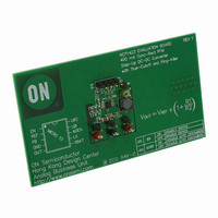
NCP1423EVB
Description
EVAL BOARD FOR NCP1423
Manufacturer
ON Semiconductor
Specifications of NCP1423EVB
Design Resources
NCP1423 Demo Board BOM NCP1423EVB Gerber Files NCP1423EVB Schematic
Main Purpose
DC/DC, Step Up
Outputs And Type
1, Non-Isolated
Voltage - Output
3.3V
Current - Output
400mA
Voltage - Input
2.5V
Regulator Topology
Boost
Frequency - Switching
600kHz
Board Type
Fully Populated
Utilized Ic / Part
NCP1423
Lead Free Status / RoHS Status
Lead free / RoHS Compliant
Power - Output
-
Lead Free Status / Rohs Status
Lead free / RoHS Compliant
For Use With/related Products
NCP1423
Other names
NCP1423EVBOS


step−up voltage switching converter IC specially designed
for battery operated hand−held electronic products up to
200 mA loading. It integrates a Synchronous Rectifier to
improving efficiency as well as to eliminate the external
Schottky diode. High switching frequency (up to 600 kHz)
allows for a low profile inductor and output capacitor to be
used. Low−Battery Detector, Logic−Controlled Shutdown
and Cycle−by−Cycle Current Limit provide value−added
features for various battery−operated applications. With all
these functions ON, the quiescent supply current is typical
only 9 mA typical. This device is available in compact
Micro10 package.
PFM Regulation Scheme
voltage is divided down and fed back to Pin 3 (FB). This
voltage goes to the non−inverting input of the PFM
comparator whereas the comparator’s inverting input is
connected to the internal voltage reference, REF. A
switching cycle is initiated by the falling edge of the
comparator, at the moment the main switch (M1) is turned
ON. After the maximum ON−time (typical 1.4 mS) elapses
or the current limit is reached, M1 is turned OFF, and the
synchronous switch (M2) is turned ON. The M1 OFF time
is not less than the minimum OFF−time (typically 0.20 mS),
which ensure complete energy transfer from the inductor to
the output capacitor. If the regulator is operating in
continuous conduction mode (CCM), M2 is turned OFF just
before M1 is supposed to be ON again. If the regulator is
operating in discontinuous conduction mode (DCM), which
means the coil current will decrease to zero before the new
cycle start, M1 is turned OFF as the coil current is almost
reaching zero. The comparator (ZLC) with fixed offset is
dedicated to sense the voltage drop across M2 as it is
conducting, when the voltage drop is below the offset, the
ZLC comparator output goes HIGH, and M2 is turned OFF.
Negative feedback of closed loop operation regulates
voltage at Pin 3 (FB) equal to the internal divide down
reference voltage times (0.5 V).
Synchronous Rectification
Diode to reduce the conduction loss contributed by the
forward voltage of the Schottky Diode. The Synchronous
Rectifier is normally realized by PowerFET with gate
control circuitry that incorporates relatively complicated
timing concerns.
synchronous switch M2 is just turned ON with M1 not being
completely turned OFF, current is shunt from the output bulk
capacitor through M2 and M1 to ground. This power loss
lowers overall efficiency and possibly damage the switching
FETs. As a general practice, certain amount of dead time is
NCP1423 is a monolithic micropower high−frequency
From the detailed block diagram (Figure 2), the output
The Synchronous Rectifier is used to replace the Schottky
As the main switch (M1) is being turned OFF and the
DETAILED OPERATION DESCRIPTION
http://onsemi.com
NCP1423
10
introduced to make sure M1 is completely turned OFF
before M2 is being turned ON.
regulator is operating in CCM, M2 is being turned OFF, M1
is just turned ON, and M2 is not being completely turned
OFF, A dead time is also needed to make sure M2 is
completely turned OFF before M1 is being turned ON.
operating in DCM, M2 should be OFF. If this does not occur,
the reverse current flows from the output bulk capacitor
through M2 and the inductor to the battery input, causing
damage to the battery. The ZLC comparator comes with
fixed offset voltage to switch M2 OFF before any reverse
current builds up. However, if M2 switch OFF too early,
large residue coil current flows through the body diode of
M2 and increases conduction loss. Therefore, determination
on the offset voltage is essential for optimum performance.
With the implementation of synchronous rectification
scheme, efficiency can be as high as 90% with this device.
Cycle−by−Cycle Current Limit
as M1 is ON. With that sample current flowing through a
sense resistor, a sense−voltage is developed. Threshold
detector (I
than the preset level. If the sense voltage is higher than the
present level, the detector output notifies the Control Logic
to switch OFF M1, and M1 can only be switched ON when
the next cycle starts after the minimum OFF−time (typically
0.20 mS). With proper sizing of SENSEFET and sense
resistor, the peak coil current limit is typically set at 1.2 A.
Voltage Reference
up to 2.5 mA with load regulation ±2.0%, at V
3.3 V. If V
be increased. A bypass capacitor of 200 nF is required for
proper operation when REF is not loaded. If REF is loaded,
1.0 mF capacitor at REF pin is needed.
True−Cutoff
the EN pin (Pin 1). Internal circuitry can isolate the current
through the body diode of switch M2 to load. Thus, it can
eliminate leakage current from the battery to load in
shutdown mode and significantly reduces battery current
consumption during shutdown. The shutdown function is
controlled by the voltage at Pin 1 (EN). When Pin 1 is pulled
to lower than 0.5 V, the controller enters shutdown mode. In
shutdown mode, when the switches M1 and M2 are both
switched OFF, the internal reference voltage of the
controller is disable and the controller typically consumes
only 600 nA of current. If the Pin 1 voltage is raised to higher
than 0.5 V, for example, by a resistor connected to V
The previously mentioned situation occurs when the
As coil current is dropped to zero when the regulator is
In Figure 2, SENSEFET is used to sample the coil current
The voltage at REF is typically set at 1.2 V and can output
The NCP1423 has a True−Cutoff function controlled by
OUT
LIM
) detects whether the sense−voltage is higher
is increased, the REF load capability can also
OUT
equal to
IN
, the
Related parts for NCP1423EVB
Image
Part Number
Description
Manufacturer
Datasheet
Request
R

Part Number:
Description:
400 Ma Sync-rect Pfm Stepup Dcdc Converter With Truecutoff And Ringkiller
Manufacturer:
ON Semiconductor
Datasheet:
Part Number:
Description:
ON Semiconductor [VOLTAGE REGULATOR]
Manufacturer:
ON Semiconductor
Datasheet:
Part Number:
Description:
357-036-542-201 CARDEDGE 36POS DL .156 BLK LOPRO
Manufacturer:
ON Semiconductor
Datasheet:
Part Number:
Description:
357-036-542-201 CARDEDGE 36POS DL .156 BLK LOPRO
Manufacturer:
ON Semiconductor
Datasheet:
Part Number:
Description:
357-036-542-201 CARDEDGE 36POS DL .156 BLK LOPRO
Manufacturer:
ON Semiconductor
Datasheet:
Part Number:
Description:
357-036-542-201 CARDEDGE 36POS DL .156 BLK LOPRO
Manufacturer:
ON Semiconductor
Datasheet:
Part Number:
Description:
357-036-542-201 CARDEDGE 36POS DL .156 BLK LOPRO
Manufacturer:
ON Semiconductor
Datasheet:
Part Number:
Description:
357-036-542-201 CARDEDGE 36POS DL .156 BLK LOPRO
Manufacturer:
ON Semiconductor
Datasheet:
Part Number:
Description:
357-036-542-201 CARDEDGE 36POS DL .156 BLK LOPRO
Manufacturer:
ON Semiconductor
Datasheet:
Part Number:
Description:
357-036-542-201 CARDEDGE 36POS DL .156 BLK LOPRO
Manufacturer:
ON Semiconductor
Datasheet:
Part Number:
Description:
357-036-542-201 CARDEDGE 36POS DL .156 BLK LOPRO
Manufacturer:
ON Semiconductor
Datasheet:
Part Number:
Description:
357-036-542-201 CARDEDGE 36POS DL .156 BLK LOPRO
Manufacturer:
ON Semiconductor
Datasheet:
Part Number:
Description:
Manufacturer:
ON Semiconductor
Datasheet:
Part Number:
Description:
Manufacturer:
ON Semiconductor
Datasheet: