LM5088MH-2EVAL National Semiconductor, LM5088MH-2EVAL Datasheet - Page 15
LM5088MH-2EVAL
Manufacturer Part Number
LM5088MH-2EVAL
Description
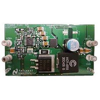
BOARD EVALUATION FOR LM5088MH-2
Manufacturer
National Semiconductor
Series
PowerWise®r
Specifications of LM5088MH-2EVAL
Design Resources
LM(2)5088-1/2 QS Component Calculator
Main Purpose
DC/DC, Step Down
Outputs And Type
1, Non-Isolated
Voltage - Output
5V
Current - Output
7A
Voltage - Input
5.5 ~ 55V
Regulator Topology
Buck
Frequency - Switching
250kHz
Board Type
Fully Populated
Utilized Ic / Part
LM5088
Silicon Manufacturer
National
Silicon Core Number
LM5088
Kit Application Type
Power Management - Voltage Regulator
Application Sub Type
Buck Controller
Kit Contents
Board, Doc
Lead Free Status / RoHS Status
Lead free / RoHS Compliant
Power - Output
-


the drain to source voltage of the buck FET when it is turned
ON, if the V
FET immediately. This feature will help protect the buck FET
in catastrophic conditions such as a sudden saturation of the
inductor.
Overload Protection Timer
(LM5088-2 Only)
To further protect the external circuitry during a prolonged
over current condition, the LM5088-2 provides a current limit
timer to disable the switching regulator and provide a delay
before restarting (hiccup mode). The number of current limit
events required to trigger the restart mode is programmed by
an external capacitor at the RES pin. During each PWM cycle,
as shown in Figure 8, the LM5088 either sinks current from
or sources current into the RES capacitor. If the emulated
current ramp exceeds the 1.2V current limit threshold, the
present PWM cycle is terminated and the LM5088 sources 50
µA into the RES pin capacitor during the next PWM clock cy-
cle. If a current limit event is not detected in a given PWM
cycle, the LM5088 disables the 50 µA source current and
sinks 27 µA from the RES pin capacitor during the next cycle.
In an overload condition, the LM5088 protects the converter
with cycle-by-cycle current limiting until the voltage at RES
pin reaches 1.2V. When RES reaches 1.2V, a hiccup mode
sequence is initiated as follows:
•
•
•
The SS capacitor is fully discharged.
The RES capacitor is discharged with 1.2 µA
Once the RES capacitor reaches 0.2V, a normal soft-start
sequence begins. This provides a time delay before
restart.
DS
exceeds 1.5V, the comparator turns off the buck
FIGURE 7. Current Limit Restart Circuit
15
•
•
The overload protection timer is very versatile and can be
configured for the following modes of protection:
1.
2.
3.
If the overload condition persists after restart, the cycle
repeats.
If the overload condition no longer exists after restart, the
RES pin is held at ground by the 27 µA discharge current
source and normal operation resumes.
1. Cycle-by-Cycle only: The hiccup mode can be
completely disabled by connecting the RES pin to GND.
In this configuration, the cycle-by-cycle protection will
limit the output current indefinitely and no hiccup
sequence will occur.
2. Delayed Hiccup: Connecting a capacitor to the RES
pin provides a programmed number of cycle-by-cycle
current limit events before initiating a hiccup mode
restart, as previously described. The advantage of this
configuration is that a short term overload will not cause
a hiccup mode restart but during extended overload
conditions, the average dissipation of the power
converter will be very low.
3. Externally Controlled Hiccup: The RES pin can also
be used as an input. By externally driving the pin to a level
greater than the 1.2V hiccup threshold, the controller will
be forced into the delayed restart sequence. For
example, the external trigger for a delayed restart
sequence could come from an over-temperature
protection or an output over-voltage sensor.
30083916
www.national.com
Related parts for LM5088MH-2EVAL
Image
Part Number
Description
Manufacturer
Datasheet
Request
R

Part Number:
Description:
IC BUCK ADJ 10A TSSOP16EP
Manufacturer:
National Semiconductor
Datasheet:
Part Number:
Description:
IC BUCK ADJ 10A TSSOP16EP
Manufacturer:
National Semiconductor
Datasheet:

Part Number:
Description:
LM5088MH-1 EVAL BOARD
Manufacturer:
National Semiconductor
Datasheet:
Part Number:
Description:
BOARD EVALUATION FOR LM5088MH-1
Manufacturer:
National Semiconductor
Datasheet:

Part Number:
Description:
Wide Input Range Non-Synchronous Buck Controller
Manufacturer:
NSC [National Semiconductor]
Datasheet:
Part Number:
Description:
National Semiconductor [8-Bit D/A Converter]
Manufacturer:
National Semiconductor
Datasheet:
Part Number:
Description:
National Semiconductor [Media Coprocessor]
Manufacturer:
National Semiconductor
Datasheet:
Part Number:
Description:
Digitally Controlled Tone and Volume Circuit with Stereo Audio Power Amplifier, Microphone Preamp Stage and National 3D Sound
Manufacturer:
National Semiconductor
Datasheet:
Part Number:
Description:
Digitally Controlled Tone and Volume Circuit with Stereo Audio Power Amplifier, Microphone Preamp Stage and National 3D Sound
Manufacturer:
National Semiconductor
Datasheet:
Part Number:
Description:
AC97 Rev 2 Codec with Sample Rate Conversion and National 3D Sound
Manufacturer:
National Semiconductor
Part Number:
Description:
Manufacturer:
National Semiconductor
Datasheet:
Part Number:
Description:
Manufacturer:
National Semiconductor
Datasheet:
Part Number:
Description:
General Purpose, Low Voltage, Low Power, Rail-to-Rail Output Operational Amplifiers
Manufacturer:
National Semiconductor
Datasheet:
Part Number:
Description:
8-bit 20 MSPS flash A/D converter.
Manufacturer:
National Semiconductor
Datasheet: