551011367-011/NOPB National Semiconductor, 551011367-011/NOPB Datasheet - Page 12
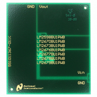
551011367-011/NOPB
Manufacturer Part Number
551011367-011/NOPB
Description
BOARD WEBENCH BUILD IT LM2598
Manufacturer
National Semiconductor
Series
WEBENCH® Buildit Boardr
Datasheet
1.LM2598T-12NOPB.pdf
(33 pages)
Specifications of 551011367-011/NOPB
Main Purpose
DC/DC, Step Down
Regulator Topology
Buck
Board Type
Bare (Unpopulated)
Utilized Ic / Part
LM2598, LM2670, LM2673, LM2676, LM2677, LM2678, LM2679
Lead Free Status / RoHS Status
Lead free / RoHS Compliant
Current - Output
-
Voltage - Output
-
Voltage - Input
-
Power - Output
-
Frequency - Switching
-
Outputs And Type
-
Other names
*551011367-011
*551011367-011/NOPB
551011367-011
*551011367-011/NOPB
551011367-011


www.national.com
LM2598 Series Buck Regulator Design Procedure (Fixed Output)
4. Input Capacitor (C
A low ESR aluminum or tantalum bypass capacitor is needed
between the input pin and ground to prevent large voltage
transients from appearing at the input. In addition, the RMS
current rating of the input capacitor should be selected to be
at least
data sheet must be checked to assure that this current rating
is not exceeded. The curve shown in Figure 16 shows typical
RMS current ratings for several different aluminum electro-
lytic capacitor values.
This capacitor should be located close to the IC using short
leads and the voltage rating should be approximately 1.5
times the maximum input voltage.
If solid tantalum input capacitors are used, it is recomended
that they be surge current tested by the manufacturer.
Use caution when using ceramic capacitors for input bypass-
ing, because it may cause severe ringing at the V
For additional information, see section on input capaci-
tors in Application Information section.
Voltage
Output
3.3
(V)
12
5
PROCEDURE (Fixed Output Voltage Version)
1
⁄
2
the DC load current. The capacitor manufacturers
Conditions
Current
Load
(A)
0.5
0.5
0.5
1
1
1
IN
FIGURE 2. LM2598 Fixed Voltage Quick Design Component Selection Table
Max Input
)
Voltage
(V)
10
40
10
40
10
15
40
20
40
15
18
30
40
15
20
40
5
7
6
8
9
Inductance
(µH)
100
100
150
150
150
220
150
330
22
33
47
68
47
68
33
47
68
68
47
68
68
Inductor
IN
Inductor
pin.
L24
L23
L31
L30
L13
L21
L20
L28
L31
L30
L29
L21
L19
L19
L31
L30
L36
L35
L21
L19
L26
( # )
12
Through Hole Electrolytic
HFQ Series
Panasonic
4. Input Capacitor (C
The important parameters for the Input capacitor are the
input voltage rating and the RMS current rating. With a
nominal input voltage of 12V, an aluminum electrolytic ca-
pacitor with a voltage rating greater than 18V (1.5 x V
would be needed. The next higher capacitor voltage rating is
25V.
The RMS current rating requirement for the input capacitor in
a buck regulator is approximately
this example, with a 1A load, a capacitor with a RMS current
rating of at least 500 mA is needed. The curves shown in
Figure 16 can be used to select an appropriate input capaci-
tor. From the curves, locate the 25V line and note which
capacitor values have RMS current ratings greater than 500
mA. Either a 180 µF or 220 µF, 25V capacitor could be used.
For a through hole design, a 220 µF/25V electrolytic capaci-
tor (Panasonic HFQ series or Nichicon PL series or equiva-
lent) would be adequate. other types or other manufacturers
capacitors can be used provided the RMS ripple current
ratings are adequate.
For surface mount designs, solid tantalum capacitors are
recommended. The TPS series available from AVX, and the
593D series from Sprague are both surge current tested.
330/16
270/25
220/25
180/35
220/25
150/35
150/35
330/16
220/25
180/35
180/35
180/16
120/25
100/25
220/25
180/35
180/25
(µF/V)
82/25
82/25
82/25
56/25
EXAMPLE (Fixed Output Voltage Version)
PL Series
Nichicon
330/16
270/25
220/35
220/35
220/16
150/25
330/16
220/25
180/35
120/35
180/16
120/25
100/25
220/25
120/25
180/25
(µF/V)
82/35
82/25
82/25
82/25
56/25
Output Capacitor
IN
)
Surface Mount Tantalum
AVX TPS
220/10
220/10
220/10
220/10
220/16
100/16
100/16
220/10
220/10
220/10
100/16
220/10
100/16
Series
(µF/V)
68/20
68/20
68/20
68/20
68/20
68/20
68/20
68/20
1
⁄
2
the DC load current. In
(Continued)
595D Series
Sprague
330/10
270/10
220/10
180/10
220/10
150/16
100/20
270/10
220/10
150/16
120/16
150/16
100/20
120/20
120/20
100/20
120/20
100/20
(µF/V)
68/25
68/25
68/25
IN
)
Related parts for 551011367-011/NOPB
Image
Part Number
Description
Manufacturer
Datasheet
Request
R

Part Number:
Description:
WEBENCH Build It Unpopulated PCB For LM2598
Manufacturer:
National Semiconductor

Part Number:
Description:
BOARD WEBENCH LM2577,LM2585/87
Manufacturer:
National Semiconductor
Datasheet:

Part Number:
Description:
BOARD WEBENCH BUILD IT LM2586/88
Manufacturer:
National Semiconductor
Datasheet:

Part Number:
Description:
BOARD WEBENCH BUILD IT
Manufacturer:
National Semiconductor
Datasheet:

Part Number:
Description:
BOARD WEBENCH BUILD IT LM2599
Manufacturer:
National Semiconductor
Datasheet:

Part Number:
Description:
BOARD WEBENCH BUILD IT LM2595
Manufacturer:
National Semiconductor
Datasheet:

Part Number:
Description:
BOARD WEBENCH BUILD IT LM2586/88
Manufacturer:
National Semiconductor
Datasheet:
Part Number:
Description:
LM2577/86 BUILD IT BOARD
Manufacturer:
National Semiconductor
Part Number:
Description:
LM2585/8 BUILD IT BOARD
Manufacturer:
National Semiconductor
Part Number:
Description:
National Semiconductor [8-Bit D/A Converter]
Manufacturer:
National Semiconductor
Datasheet:
Part Number:
Description:
National Semiconductor [Media Coprocessor]
Manufacturer:
National Semiconductor
Datasheet:
Part Number:
Description:
Digitally Controlled Tone and Volume Circuit with Stereo Audio Power Amplifier, Microphone Preamp Stage and National 3D Sound
Manufacturer:
National Semiconductor
Datasheet:
Part Number:
Description:
Digitally Controlled Tone and Volume Circuit with Stereo Audio Power Amplifier, Microphone Preamp Stage and National 3D Sound
Manufacturer:
National Semiconductor
Datasheet:
Part Number:
Description:
AC97 Rev 2 Codec with Sample Rate Conversion and National 3D Sound
Manufacturer:
National Semiconductor
Part Number:
Description:
Manufacturer:
National Semiconductor
Datasheet: