EVL6566A-75WES4 STMicroelectronics, EVL6566A-75WES4 Datasheet - Page 27
EVL6566A-75WES4
Manufacturer Part Number
EVL6566A-75WES4
Description
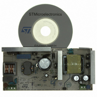
BOARD DEMO FOR L6563/LL6566A
Manufacturer
STMicroelectronics
Type
Power Factor Correctionr
Specifications of EVL6566A-75WES4
Main Purpose
AC/DC, Primary and Secondary Side with PFC
Outputs And Type
1, Isolated
Power - Output
75W
Voltage - Output
19V
Current - Output
4A
Voltage - Input
90 ~ 264VAC
Regulator Topology
Flyback
Board Type
Fully Populated
Utilized Ic / Part
L6563, L6566A, TSM1014
Input Voltage
90 V to 264 V
Output Voltage
19 V
Dimensions
78 mm x 170 mm
Product
Power Management Modules
Lead Free Status / RoHS Status
Lead free / RoHS Compliant
Frequency - Switching
-
Lead Free Status / Rohs Status
Lead free / RoHS Compliant
For Use With/related Products
L6563S, L6566A
Other names
497-8834
Available stocks
Company
Part Number
Manufacturer
Quantity
Price


L6566A
5.6
Figure 15. Externally controlled burst-mode operation by driving pin COMP: timing
PWM comparator, PWM latch and voltage feedforward blocks
The PWM comparator senses the voltage across the current sense resistor Rs and, by
comparing it to the programming signal delivered by the feedforward block, determines the
exact time when the external MOSFET is to be switched off. Its output resets the PWM
latch, previously set by the oscillator or the ZCD triggering block, which will assert the gate
driver output low. The use of PWM latch avoids spurious switching of the MOSFET that
might result from the noise generated (“double-pulse suppression”).
Cycle-by-cycle current limitation is realized with a second comparator (OCP comparator)
that senses the voltage across the current sense resistor Rs as well and compares this
voltage to a reference value V
the circuit schematic in
delivered by the feedforward block and sent to the PWM comparator exceeds V
the OCP comparator to reset first the PWM latch instead of the PWM comparator. The value
of Vcsx, thereby, determines the overcurrent setpoint along with the sense resistor Rs.
The power that QR flyback converters with a fixed overcurrent setpoint (like fixed-frequency
systems) are able to deliver changes with the input voltage considerably. Obviously, this is
not a problem if the flyback converter runs off a fixed voltage bus generated by the PFC pre-
regulator; however, with a tracking boost PFC (a “boost follower” PFC), the regulated output
voltage at maximum mains voltage can be even twice the value at minimum mains voltage.
In this case the issue is still there, although not as big as without PFC and wide-range
mains. With a 1:2 voltage change, the maximum transferable power at maximum line can be
50 % higher than at minimum line, as shown by the upper curve in the diagram of
The L6566A has the line feedforward function available to solve this issue.
diagram
Vcc_PFC
0.85 mA
Vcc_OK
(pin 6)
Vcc
Vout
COMP
(pin 9)
(pin 5)
(pin 4)
I
Vcc
charge
Vcc
Vcc
GD
restart
OFF
ON
Figure 17 on page 29
CSX
Standby is commanded here
. Its output is or-ed with that of the PWM comparator (see
). In this way, if the programming signal
Application information
t
t
t
t
t
t
t
CSX
Figure 16
, it will be
27/51
.
Related parts for EVL6566A-75WES4
Image
Part Number
Description
Manufacturer
Datasheet
Request
R

Part Number:
Description:
BOARD EVAL FOR L6566A
Manufacturer:
STMicroelectronics
Datasheet:

Part Number:
Description:
STMicroelectronics [RIPPLE-CARRY BINARY COUNTER/DIVIDERS]
Manufacturer:
STMicroelectronics
Datasheet:
Part Number:
Description:
STMicroelectronics [LIQUID-CRYSTAL DISPLAY DRIVERS]
Manufacturer:
STMicroelectronics
Datasheet:

Part Number:
Description:
BOARD EVAL FOR MEMS SENSORS
Manufacturer:
STMicroelectronics
Datasheet:
Part Number:
Description:
NPN TRANSISTOR POWER MODULE
Manufacturer:
STMicroelectronics
Datasheet:
Part Number:
Description:
TURBOSWITCH ULTRA-FAST HIGH VOLTAGE DIODE
Manufacturer:
STMicroelectronics
Datasheet:
Part Number:
Description:
Manufacturer:
STMicroelectronics
Datasheet:
Part Number:
Description:
DIODE / SCR MODULE
Manufacturer:
STMicroelectronics
Datasheet:
Part Number:
Description:
DIODE / SCR MODULE
Manufacturer:
STMicroelectronics
Datasheet:
Part Number:
Description:
Search -----> STE16N100
Manufacturer:
STMicroelectronics
Datasheet:
Part Number:
Description:
Search ---> STE53NA50
Manufacturer:
STMicroelectronics
Datasheet:
Part Number:
Description:
NPN Transistor Power Module
Manufacturer:
STMicroelectronics
Datasheet: