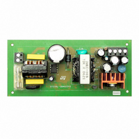
STEVAL-ISA023V2 STMicroelectronics, STEVAL-ISA023V2 Datasheet - Page 17
STEVAL-ISA023V2
Manufacturer Part Number
STEVAL-ISA023V2
Description
EVAL BOARD 24W NEG OUT VIPER53E
Manufacturer
STMicroelectronics
Series
VIPER™r
Type
AC/DC Switching Convertersr
Specifications of STEVAL-ISA023V2
Mfg Application Notes
VIPer53EDIP - AppNote
Design Resources
STEVAL-ISA023V2 Gerber Files STEVAL-ISA023V2 Schematic STEVAL-ISA023V2 Bill of Materials
Main Purpose
AC/DC, Primary Side
Outputs And Type
2, Isolated
Power - Output
24W
Voltage - Output
-5V, -12V
Current - Output
3A, 800mA
Voltage - Input
90 ~ 265VAC
Regulator Topology
Flyback
Frequency - Switching
60kHz
Board Type
Fully Populated
Utilized Ic / Part
VIPer53
Input Voltage
90 V to 265 V
Output Voltage
- 5 V, - 12 V
Product
Power Management Modules
Silicon Manufacturer
ST Micro
Silicon Core Number
VIPer53-E
Kit Application Type
Power Management
Application Sub Type
SMPS
Kit Contents
Board
Lead Free Status / RoHS Status
Lead free / RoHS Compliant
For Use With/related Products
VIPer53-E
Other names
497-5866
Available stocks
Company
Part Number
Manufacturer
Quantity
Price
Company:

Part Number:
STEVAL-ISA023V2
Manufacturer:
STMicroelectronics
Quantity:
1


VIPer53 - E
6
Secondary feedback configuration example
When a more accurate output voltage is needed, the way is to monitor it directly secondary
side, and drive the PWM controller through an optocoupler as shown on
The optocoupler is connected in parallel with the compensation network on the COMP pin.
The design of the auxiliary winding that the VDD voltage is always lower than the internal
15V reference. The internal error amplifier will therefore be saturated in the high state, and
because of its transconductance nature, will deliver a constant biasing current of 0.6mA to
the optotransistor. This current does not depend on the compensation voltage, and so it
does not depend on the output load either. Consequently, the gain of the optocoupler
ensures consequently a constant biasing of the TL431 device (U3) which is in charge of
secondary regulation. If the optocoupler gain is sufficiently low, no additional components
are required to ensure a minimum current biasing of U3. Also, the low biasing current value
avoid any ageing of the optocoupler.
The constant current biasing can be used to simplify the secondary circuit: Instead of a
TL431, a simple zener and resistance network in series with the optocoupler diode can
insure a good secondary regulation. As the current flowing in this branch remains constant
for the same reason as above, typical load regulation of 1% can be achieved from zero to full
output current with this simple configuration.
Figure 19. Off line power supply with optocoupler feedback
AC IN
F1
R1
C1
C4
R3
C5
OSC
T1
VIPer73
U1
15V
TOVL
VDD
R9
1k
C6
D1
10nF
C11
COMP
R4
SOURCE
R5
C7
C2
DRAIN
Secondary feedback configuration example
C3
D2
D3
R2
T2
D4
U2
U3
C10
C8
R8
Figure 17.
L1
C12
R7
R6
C9
17/36
DC OUT
Related parts for STEVAL-ISA023V2
Image
Part Number
Description
Manufacturer
Datasheet
Request
R

Part Number:
Description:
BOARD RGB CTR ST7,STP08C596MTR
Manufacturer:
STMicroelectronics
Datasheet:

Part Number:
Description:
Power Management IC Development Tools Full Speed USB to RS232 Bridge Demo
Manufacturer:
STMicroelectronics
Datasheet:
Part Number:
Description:
Power Management IC Development Tools 2.5W solar eval BRD USB SPV1040 LD39050
Manufacturer:
STMicroelectronics
Datasheet:

Part Number:
Description:
BOARD EVAL FOR MEMS SENSORS
Manufacturer:
STMicroelectronics
Datasheet:

Part Number:
Description:
KIT DEV STARTER ST10F276Z5
Manufacturer:
STMicroelectronics
Datasheet:

Part Number:
Description:
BOARD EVAL HDMI $ VIDEO SWITCH
Manufacturer:
STMicroelectronics
Datasheet:

Part Number:
Description:
BOARD DEMO ACCELEROMETER DIL24
Manufacturer:
STMicroelectronics
Datasheet:

Part Number:
Description:
BOARD STLM75/STDS75/ST72F651
Manufacturer:
STMicroelectronics
Datasheet:

Part Number:
Description:
EVAL BOARD 3AXIS MEMS ACCELLRMTR
Manufacturer:
STMicroelectronics
Datasheet:

Part Number:
Description:
BOARD EVAL 8BIT MICRO + TDE1708
Manufacturer:
STMicroelectronics
Datasheet:
Part Number:
Description:
STMicroelectronics [RIPPLE-CARRY BINARY COUNTER/DIVIDERS]
Manufacturer:
STMicroelectronics
Datasheet:
Part Number:
Description:
STMicroelectronics [LIQUID-CRYSTAL DISPLAY DRIVERS]
Manufacturer:
STMicroelectronics
Datasheet:
Part Number:
Description:
BOARD EVAL FOR MEMS SENSORS
Manufacturer:
STMicroelectronics
Datasheet: