EVL6566B-40WSTB STMicroelectronics, EVL6566B-40WSTB Datasheet - Page 32
EVL6566B-40WSTB
Manufacturer Part Number
EVL6566B-40WSTB
Description
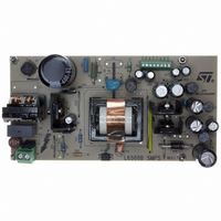
BOARD EVAL FOR L6566B
Manufacturer
STMicroelectronics
Datasheet
1.L6566BTR.pdf
(51 pages)
Specifications of EVL6566B-40WSTB
Main Purpose
AC/DC, Primary Side
Outputs And Type
4, Isolated
Power - Output
40W
Voltage - Output
5V, 12V, 1.8V, 3.3V
Current - Output
2.4A, 1.9A, 1.73A, 500mA
Voltage - Input
90 ~ 264VAC
Regulator Topology
Flyback
Frequency - Switching
62kHz
Board Type
Fully Populated
Utilized Ic / Part
L6566B
Product
Power Management Modules
Lead Free Status / RoHS Status
Lead free / RoHS Compliant
Other names
497-6450
Available stocks
Company
Part Number
Manufacturer
Quantity
Price


Application information
5.9
32/51
Equation 9
which is the parameter that the amplitude of the generated side-band harmonics depends
on.
The minimum frequency f
frequency f
around the centre value f
Equation 10
Then, R
oscillator block on page 21
Equation 11
where Δf
to achieve the best compromise between attenuation of peak EMI emissions and clean
converter operation.
Latched disable function
The device is equipped with a comparator having the non-inverting input externally available
at the pin DIS (8) and with the inverting input internally referenced to 4.5 V. As the voltage
on the pin exceeds the internal threshold, the device is immediately shut down and its
consumption reduced to a low value.
The information is latched and it is necessary to let the voltage on the Vcc pin go below the
UVLO threshold to reset the latch and restart the device. To keep the latch supplied as long
as the converter is connected to the input source, the HV generator is activated periodically
so that Vcc oscillates between the start-up threshold V
HV generator in this way cuts its power dissipation approximately by three (as compared to
the case of continuous conduction) and keeps peak silicon temperature close to the average
value.
To let the L6566B restart it is then necessary to disconnect the converter from the input
source. Pulling pin 16 (AC_OK) below the disable threshold (see
protection on page 37
latch can be cleared and a quicker restart is allowed as the input source is removed. This
operation is shown in the timing diagram of
T
sw
will be found from (5) (see
sw_max
and f
m
(occurring on the valley of the triangle) will be symmetrically placed
(in kHz, with C
) will stop the HV generator until Vcc falls below Vcc
f
sw
sw
_
sw_min
min
), while R
, so that:
R
MOD
=
f
sw
(occurring on the peak of the triangle) and the maximum
MOD
=
−
Section 5.2: Zero current detection and triggering block;
MOD
2
2
1
Δ
in nF and R
⋅
Δ
10
f
sw
f
sw
and C
β
3
;
=
Figure 20 on page 33
f Δ
f
m
MOD
sw
C
f
sw
MOD
MOD
_
can be calculated as follows:
max
ccON
in kΩ) will be selected by the user so
=
=
75
f
m
f
sw
and V
+
2
1
ccON
Section 5.12: Brownout
.
Δ
f
sw
- 0.5 V. Activating the
restart
, so that the
L6566B
Related parts for EVL6566B-40WSTB
Image
Part Number
Description
Manufacturer
Datasheet
Request
R

Part Number:
Description:
BOARD EVAL SMPS FOR L6566B
Manufacturer:
STMicroelectronics
Datasheet:

Part Number:
Description:
BOARD EVAL FOR L6566B
Manufacturer:
STMicroelectronics
Datasheet:

Part Number:
Description:
BOARD EVAL FOR L6566B
Manufacturer:
STMicroelectronics
Datasheet:

Part Number:
Description:
Power Management Modules & Development Tools L6566B-60WQR Eval Board
Manufacturer:
STMicroelectronics
Part Number:
Description:
STMicroelectronics [RIPPLE-CARRY BINARY COUNTER/DIVIDERS]
Manufacturer:
STMicroelectronics
Datasheet:
Part Number:
Description:
STMicroelectronics [LIQUID-CRYSTAL DISPLAY DRIVERS]
Manufacturer:
STMicroelectronics
Datasheet:

Part Number:
Description:
BOARD EVAL FOR MEMS SENSORS
Manufacturer:
STMicroelectronics
Datasheet:
Part Number:
Description:
NPN TRANSISTOR POWER MODULE
Manufacturer:
STMicroelectronics
Datasheet:
Part Number:
Description:
TURBOSWITCH ULTRA-FAST HIGH VOLTAGE DIODE
Manufacturer:
STMicroelectronics
Datasheet:
Part Number:
Description:
Manufacturer:
STMicroelectronics
Datasheet:
Part Number:
Description:
DIODE / SCR MODULE
Manufacturer:
STMicroelectronics
Datasheet:
Part Number:
Description:
DIODE / SCR MODULE
Manufacturer:
STMicroelectronics
Datasheet: