MCP1612EV Microchip Technology, MCP1612EV Datasheet - Page 13
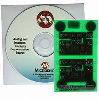
MCP1612EV
Manufacturer Part Number
MCP1612EV
Description
BOARD EVAL FOR MCP1612
Manufacturer
Microchip Technology
Type
DC/DC Switching Converters, Regulators & Controllersr
Specifications of MCP1612EV
Main Purpose
DC/DC, Step Down
Outputs And Type
1, Non-Isolated
Voltage - Output
0.8V, 1V, 1.2V, 1.4V, 1.7V, 2.4V or 3.3V
Current - Output
1A
Voltage - Input
2.7 ~ 5.5V
Regulator Topology
Buck
Frequency - Switching
1.4MHz
Board Type
Fully Populated
Utilized Ic / Part
MCP1612
Input Voltage
2.7 V to 5.5 V
Output Voltage
0.8 V to 3.3 V
Product
Power Management Modules
For Use With/related Products
MCP1612
Lead Free Status / RoHS Status
Contains lead / RoHS non-compliant
Power - Output
-
Lead Free Status / Rohs Status
Lead free / RoHS Compliant
Available stocks
Company
Part Number
Manufacturer
Quantity
Price
Company:

Part Number:
MCP1612EV
Manufacturer:
MICROCHIP
Quantity:
12 000


Solving for C:
There will also be some ripple voltage caused by the
ESR of the capacitor. The ripple is defined as follows.
EQUATION 5-7:
For this example:
5.2.4
For the buck topology, the input current is pulled from
the source and the input capacitor in pulses. The size
of the input capacitor will determine the amount of
current pulled from the source. For most applications,
a 10 µF ceramic capacitor connected between the
MCP1612’s V
current pulses. Less capacitance can be used for
applications that have low source impedance. The
ripple current rating for ceramic capacitors are typically
very high due to their low loss characteristics. Low-cost
electrolytic capacitors can be used, but their ripple
current rating should not be exceeded.
5.2.5
The V
circuitry. A 10
unregulated inputs V
capacitor to ground to help isolate the V
switching noise.
© 2005 Microchip Technology Inc.
Where:
V
V
CC
ESRRIPPLE
ESRRIPPLE
V
I
input is used to bias the internal MCP1612
C
C
t = on-time of P-channel MOSFET
INPUT CAPACITOR
V
V
V
V
ESR = 8 m
= peak-to-peak ripple current
= output ripple voltage
CC
OUT
OUT
OUT
IN
V
V
V
I
C = 4.7 µF
C
C
C
and P
resistor is recommended between the
t = 260 ns
ESRRIPPLE
INPUT
= 165 mA
= (260 ns x 165 mA)/4.7 µF
= 9.13 mV
= 8 m x 165 mA
= 1.32 mV
=
= 9.13 mV + 1.32 mV
= 10.45 mV
C
IN
GND
=
V
and V
I
C
C
is recommended to filter the
+ V
=
---------- -
ESR
CC
ESRRIPPLE
V
t
C
, along with a 0.1 µF
I
C
CC
pin from the
5.2.6
An internal transconductance error amplifier is used to
compensate the buck converter. An external resistor
(R
and GND, are all that is needed to provide a high-
bandwidth loop.
Table 5-1 identifies values for R
buck inductor (L) and output capacitor (C
TABLE 5-1:
5.3
The MCP1612 is capable of switching over 1A at
1.4 MHz. As with all high-frequency switching power
supplies, good PCB layout techniques are essential to
prevent noise generated by the switching power-train
from interfering with the sensing circuitry.
There are two ground pins (P
MCP1612 to separate the large-signal ground current
from the small-signal circuit ground. These two
grounds should be kept separate, only connecting near
the input bulk capacitor.
Care must also be taken to minimize the length and
loop area of the large signal connections. Components
connected to this loop consist of the input bulk
capacitor, V
buck inductor and the output filter capacitor.
C
3.3 µH
2.2 µH
) and capacitor (C
L
Printed Circuit Board (PCB)
Layout
COMPENSATION COMPONENTS
IN
, P
GND
10.0 µF
4.7 µF
C
R
OUT
C
and L
and C
C
), connected between COMP
X
C
pins of the MCP1612, the
VALUES
MCP1612
GND
25 k
10 k
C
R
and C
C
and A
DS21921B-page 13
C
OUT
GND
for standard
1000 pF
1000 pF
) values.
C
) on the
C
Related parts for MCP1612EV
Image
Part Number
Description
Manufacturer
Datasheet
Request
R

Part Number:
Description:
Manufacturer:
Microchip Technology Inc.
Datasheet:
Part Number:
Description:
Manufacturer:
Microchip Technology Inc.
Datasheet:
Part Number:
Description:
Manufacturer:
Microchip Technology Inc.
Datasheet:
Part Number:
Description:
Manufacturer:
Microchip Technology Inc.
Datasheet:
Part Number:
Description:
Manufacturer:
Microchip Technology Inc.
Datasheet:
Part Number:
Description:
Manufacturer:
Microchip Technology Inc.
Datasheet:
Part Number:
Description:
Manufacturer:
Microchip Technology Inc.
Datasheet:
Part Number:
Description:
Manufacturer:
Microchip Technology Inc.
Datasheet: