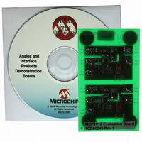
MCP1612EV Microchip Technology, MCP1612EV Datasheet - Page 12

MCP1612EV
Manufacturer Part Number
MCP1612EV
Description
BOARD EVAL FOR MCP1612
Manufacturer
Microchip Technology
Type
DC/DC Switching Converters, Regulators & Controllersr
Specifications of MCP1612EV
Main Purpose
DC/DC, Step Down
Outputs And Type
1, Non-Isolated
Voltage - Output
0.8V, 1V, 1.2V, 1.4V, 1.7V, 2.4V or 3.3V
Current - Output
1A
Voltage - Input
2.7 ~ 5.5V
Regulator Topology
Buck
Frequency - Switching
1.4MHz
Board Type
Fully Populated
Utilized Ic / Part
MCP1612
Input Voltage
2.7 V to 5.5 V
Output Voltage
0.8 V to 3.3 V
Product
Power Management Modules
For Use With/related Products
MCP1612
Lead Free Status / RoHS Status
Contains lead / RoHS non-compliant
Power - Output
-
Lead Free Status / Rohs Status
Lead free / RoHS Compliant
Available stocks
Company
Part Number
Manufacturer
Quantity
Price
Company:
Part Number:
MCP1612EV
Manufacturer:
MICROCHIP
Quantity:
12 000
MCP1612
5.2.2
There are many requirements that need to be satisfied
when selecting the buck inductor. The application,
physical size, current rating, resistance, mounting
method,
inductance and cost all need to be considered.
Many suppliers specify the maximum peak current that
an inductor can handle before magnetic saturation
occurs. The peak current is equal to the maximum DC
output current, plus one-half the peak-to-peak AC
ripple current.
When the P-channel MOSFET is on, the current in the
buck inductor is ramped up. The voltage across the
inductor, the inductance and the MOSFET on-time are
required to determine the peak-to-peak ripple current.
When operating in Continuous Current mode, the on-
time of the P-channel MOSFET is determined by
multiplying the duty cycle by the switching period. The
following equation can be used to determine the duty
cycle.
EQUATION 5-2:
The on-time is then defined as follows.
EQUATION 5-3:
The AC ripple current in the inductor can be calculated
by the following relationship.
EQUATION 5-4:
Solving for I
EQUATION 5-5:
DS21921B-page 12
Where:
Where:
F
V
SW
L
t = on-time of the P-channel MOSFET
= voltage across the inductor
= switching frequency
supplier,
BUCK INDUCTOR
(V
L
T
yields:
IN
DutyCycle
ON
– V
V
=
L
OUT
temperature
I
DutyCycle
L
=
=
L
)
V
----- -
=
L
L
--------
V
-------------
I
t
V
L
OUT
IN
t
--------- -
F
range,
1
SW
minimum
The value of the buck inductor is chosen to be 3.3 µH.
The AC ripple current is controlled by the size of the
buck inductor. The value of the inductor will therefore
need to be raised so that the converter operates in
Continuous Conduction mode. Calculation of the buck
inductor current rating follows.
The inductor selected must have an inductance of
3.3 µH at a peak current rating of 1.08A. The DC resis-
tance of the inductor should be as low as is feasibly
possible. Extremely low DC resistance inductors are
available, though a trade-off between size and cost
should be considered.
5.2.3
The output capacitor is used to filter the inductor AC
ripple current and provide storage for load transients.
The size and Equivalent Series Resistance (ESR) of
the output capacitor determines the amount of ripple
voltage present at the output of the converter. When
selecting the output capacitor, a design trade-off has to
be made between the acceptable ripple voltage and the
size/cost of the output capacitor. Ceramic capacitors
have very low ESR, but increase in cost with higher
values. Tantalum and electrolytic capacitors are
relatively inexpensive in higher values, but they also
have a much higher ESR.
The amount of capacitance needed to obtain the
desired ripple voltage is calculated by using the
following relationship.
EQUATION 5-6:
I
OUT(MAX)
I
I
I
L(PEAK)
L(PEAK)
L(PEAK)
V
F
T
T
OUT
V
SW
ON
ON
V
IN
I
I
L
L
L
OUTPUT CAPACITOR
= 3.3V
= 1.2V
= 1.4 MHz
= 1A
= (1.2V/3.3V) x (1/1.4 MHz)
= 260 ns
= (3.3V – 1.2V) = 2.1V
= (2.1V/3.3 µH) x 260 ns
= 165 mA
= I
= 1A + (165 mA)/2
= 1.08A
OUT(MAX)
I
C
=
© 2005 Microchip Technology Inc.
C
+ 1/2 I
---------- -
V
t
C
L


