EVALSF3-ICE3B2065P Infineon Technologies, EVALSF3-ICE3B2065P Datasheet - Page 11
EVALSF3-ICE3B2065P
Manufacturer Part Number
EVALSF3-ICE3B2065P
Description
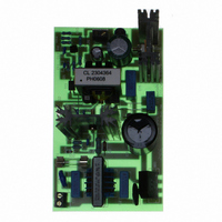
BOARD DEMO ICE3B2065P 40W SMPS
Manufacturer
Infineon Technologies
Series
CoolSET®F3r
Datasheet
1.EVALSF3-ICE3B2065P.pdf
(20 pages)
Specifications of EVALSF3-ICE3B2065P
Main Purpose
AC/DC, Primary Side
Outputs And Type
1, Isolated
Power - Output
40W
Voltage - Output
18V
Current - Output
2.22A
Voltage - Input
85 ~ 265VAC
Regulator Topology
Flyback
Frequency - Switching
67kHz
Board Type
Fully Populated
Utilized Ic / Part
ICE3B2065
Lead Free Status / RoHS Status
Lead free / RoHS Compliant
Other names
EVALSF3-ICE3B2065PIN


6.8
On the secondary side the power is coupled out by an ultra-fast diode D3. The capacitor C10 provide energy
buffering followed with the LC filter, L1 and C14 to reduce the output voltage ripple considerably. Storage
capacitor C10 is selected to have an internal resistance as small as possible (ESR) to minimize the output
voltage ripple.
6.9
The output voltage is sensed by the voltage divider of R9, R10, R8 and R8a and compare to the TL431
internal reference voltage. The output voltage of TL431, IC2 is transferred to the primary via an optocoupler,
IC1 for regulation control. The secondary regulation control is adopted with TL431 and optocoupler. C11,
C12, R5 being the compensation network constitutes the external circuitry of the error amplifier of TL431.
The circuitry allows the feedback to be precisely matched to dynamically varying load conditions, thereby
providing stable control. The maximum current through the optocoupler diode and the voltage reference is
limited by the resistor R6 and R7. Optocoupler IC1 is used for floating transmission of the control signal to
the ‘FB’ input of the ICE3B2065P. Filter capacitor C8 at FB pin of the IC3B2065P is used to eliminate the
noise.
6.10
In case of load jump the controller provides a Blanking Window before activating the Overvoltage Protection
and enters the Auto Restart Mode. The timeframe is generated by charging up the Soft Start capacitor C5
from 4.4V to 5.4V. Within this timeframe the voltage at Feedback pin can rise up above 4.8V, without
switching off. During this operation the transferred power is limited to the maximum peak current defined by
the value of the current sense resistor R3 and R4. The same procedure happens to the external Soft Start
capacitor C5 if a low load condition is detected when V
exceeded 5.4V and V
6.11
At light load condition the SMPS enters into Active Burst Mode. The controller is always active at this state.
Vcc must therefore be above the switch off threshold V
fast response on load jump, efficiency also increased significantly during Active Burst Mode. When the
voltage level at FB falls below 1.32V, Soft start capacitor C5 at SOFTST pin is allowed to charge starting
from the clamped voltage level at 4.4V in Normal Operating Mode. Active Burst Mode is entered once
V
generated to avoid a sudden entering of Burst Mode due to load jump.
During Active Burst Mode the current sense voltage limit at CS ( I
the conduction losses. All the internal circuits are switched off except the reference and bias voltages to
reduce the total V
between 3.4 and 4V. To leave Burst Mode, FB voltage must exceed 4.8V as a result of increase loading.
This resets the Active Burst Mode and turns the SMPS into Normal Operating Mode. Maximum current can
now be provided to stabilize V
Application Note
SOFTST
exceeds 5.4V. A Blanking Window as mentioned earlier which can be adjusted by manipulating C5 is
Output Stage
Feedback Loop
Blanking Window for Load Jump / Active Burst Mode
Active Burst Mode
CC
FB
current consumption to below 1.1mA. The FB voltage is changing like a sawtooth
is still below 1.32V, Active Burst Mode is activated.
OUT.
40W 18V Demoboard using ICE3B2065P on board
11
ccoff
FB
= 8.5V. While supporting low ripple on Vout and
is falling below 1.32V. Only after Vsofts has
SENSE
) pin, V
CS
, is set to 0.257V to reduce
2006-07-18
Related parts for EVALSF3-ICE3B2065P
Image
Part Number
Description
Manufacturer
Datasheet
Request
R

Part Number:
Description:
BOARD DEMO ICE3DS01G 60W SO-8
Manufacturer:
Infineon Technologies
Datasheet:

Part Number:
Description:
BOARD DEMO ICE3A5565P 100W SMPS
Manufacturer:
Infineon Technologies
Datasheet:

Part Number:
Description:
BOARD DEMO ICE3B0565 15W SMPS
Manufacturer:
Infineon Technologies
Datasheet:

Part Number:
Description:
BOARD DEMO ICE3B2565 30.4W SMPS
Manufacturer:
Infineon Technologies
Datasheet:

Part Number:
Description:
BOARD DEMO ICE3DS01 60W 8-DIP
Manufacturer:
Infineon Technologies
Datasheet:

Part Number:
Description:
BOARD DEMO ICE3B1565 20W SMPS
Manufacturer:
Infineon Technologies
Datasheet:

Part Number:
Description:
Manufacturer:
Infineon Technologies AG
Datasheet:
Part Number:
Description:
Manufacturer:
Infineon Technologies AG
Datasheet:
Part Number:
Description:
Manufacturer:
Infineon Technologies AG
Datasheet:
Part Number:
Description:
Manufacturer:
Infineon Technologies AG
Datasheet:
Part Number:
Description:
Manufacturer:
Infineon Technologies AG
Datasheet:
Part Number:
Description:
Manufacturer:
Infineon Technologies AG
Datasheet:
Part Number:
Description:
Manufacturer:
Infineon Technologies AG
Datasheet:
Part Number:
Description:
16-bit microcontroller with 2x2 KByte RAM
Manufacturer:
Infineon Technologies AG
Datasheet:
Part Number:
Description:
NPN silicon RF transistor
Manufacturer:
Infineon Technologies AG
Datasheet: