NCP1606BOOSTGEVB ON Semiconductor, NCP1606BOOSTGEVB Datasheet - Page 10
NCP1606BOOSTGEVB
Manufacturer Part Number
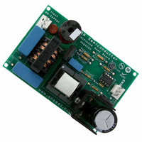
NCP1606BOOSTGEVB
Description
EVAL BOARD FOR NCP1606BOOSTG
Manufacturer
ON Semiconductor
Specifications of NCP1606BOOSTGEVB
Design Resources
NCP1606BOOST EVB BOM NCP1606BOOSTGEVB Gerber Files NCP1606BOOST EVB Schematic
Main Purpose
AC/DC, Primary and Secondary Side with PFC
Outputs And Type
1, Isolated
Power - Output
100W
Voltage - Output
400V
Current - Output
250mA
Voltage - Input
88 ~ 264VAC
Regulator Topology
Boost
Frequency - Switching
250kHz
Board Type
Fully Populated
Utilized Ic / Part
NCP1606
Lead Free Status / RoHS Status
Lead free / RoHS Compliant
For Use With/related Products
NCP1606BOOSTG
Other names
NCP1606BOOSTGEVBOS


a high frequency switching converter which regulates the
input current to stay in phase with the input voltage. These
circuits operate at a higher frequency and so they are
smaller, lighter in weight, and more efficient than a passive
circuit. With proper control of an active PFC stage, almost
any complex load can be made to appear in phase with the
topology for active power factor correction. With the
proper control, it produces a constant voltage while
drawing a sinusoidal current from the line. For medium
power (<300 W) applications, critical conduction mode
(also called borderline conduction mode) is the preferred
control method. Critical conduction mode (CRM) occurs at
the boundary between discontinuous conduction mode
AC Line
The boost (or step up) converter is the most popular
IN
The power switch being about zero, the input voltage
is applied across the coil. The coil current linearly
increases with a (V
Diode Bridge
V
Coil
Current
d
The power switch is ON
Rectifiers
+
−
in
/L) slope.
V
Figure 23. Schematic and Waveforms of an Ideal CRM Boost Converter
in
+
Figure 22. Active PFC Pre−Converter with the NCP1606
+
V
L
High
Frequency
Bypass
Capacitor
in
/L
I
V
coil
d
V
OUT
I
coil_pk
http://onsemi.com
NCP1606
PFC Preconverter
IN
10
The coil current flows through the diode. The coil voltage is (V
V
in
) and the coil current linearly decays with a (V
ac line, thus significantly reducing the harmonic current
content. Because of these advantages, active PFC circuits
have become the most popular way to meet harmonic
content requirements. Generally, they consist of inserting
a PFC pre−regulator between the rectifier bridge and the
bulk capacitor (Figure 22).
(DCM) and continuous conduction mode (CCM). In CRM,
the next driver on time is initiated when the boost inductor
current reaches zero. CRM operation is an ideal choice for
medium power PFC boost stages because it combines the
lower peak currents of CCM operation with the zero current
switching of DCM operation. The operation and
waveforms in a PFC boost converter are illustrated in
Figure 23.
Diode Bridge
(V
If next cycle does not start
then V
OUT
+
−
− V
d
rings towards V
The power switch is OFF
in
+
V
)/L
in
+
Bulk
Storage
Capacitor
Critical Conduction Mode:
Next current cycle starts as
soon as the core is reset.
V
in
in
L
Converter
V
d
I
OUT
coil
− V
in
)/L slope.
+
V
OUT
OUT
Load
−
Related parts for NCP1606BOOSTGEVB
Image
Part Number
Description
Manufacturer
Datasheet
Request
R

Part Number:
Description:
Cost Effective Power Factor Controller
Manufacturer:
ON Semiconductor
Datasheet:
Part Number:
Description:
ON Semiconductor [VOLTAGE REGULATOR]
Manufacturer:
ON Semiconductor
Datasheet:
Part Number:
Description:
357-036-542-201 CARDEDGE 36POS DL .156 BLK LOPRO
Manufacturer:
ON Semiconductor
Datasheet:
Part Number:
Description:
357-036-542-201 CARDEDGE 36POS DL .156 BLK LOPRO
Manufacturer:
ON Semiconductor
Datasheet:
Part Number:
Description:
357-036-542-201 CARDEDGE 36POS DL .156 BLK LOPRO
Manufacturer:
ON Semiconductor
Datasheet:
Part Number:
Description:
357-036-542-201 CARDEDGE 36POS DL .156 BLK LOPRO
Manufacturer:
ON Semiconductor
Datasheet:
Part Number:
Description:
357-036-542-201 CARDEDGE 36POS DL .156 BLK LOPRO
Manufacturer:
ON Semiconductor
Datasheet:
Part Number:
Description:
357-036-542-201 CARDEDGE 36POS DL .156 BLK LOPRO
Manufacturer:
ON Semiconductor
Datasheet:
Part Number:
Description:
357-036-542-201 CARDEDGE 36POS DL .156 BLK LOPRO
Manufacturer:
ON Semiconductor
Datasheet:
Part Number:
Description:
357-036-542-201 CARDEDGE 36POS DL .156 BLK LOPRO
Manufacturer:
ON Semiconductor
Datasheet:
Part Number:
Description:
357-036-542-201 CARDEDGE 36POS DL .156 BLK LOPRO
Manufacturer:
ON Semiconductor
Datasheet:
Part Number:
Description:
357-036-542-201 CARDEDGE 36POS DL .156 BLK LOPRO
Manufacturer:
ON Semiconductor
Datasheet:
Part Number:
Description:
Manufacturer:
ON Semiconductor
Datasheet:
Part Number:
Description:
Manufacturer:
ON Semiconductor
Datasheet: