EVL6599A-90WADP STMicroelectronics, EVL6599A-90WADP Datasheet - Page 28
EVL6599A-90WADP
Manufacturer Part Number
EVL6599A-90WADP
Description
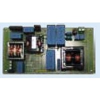
BOARD EVAL BASED ON L6599
Manufacturer
STMicroelectronics
Type
PWM Controllersr
Specifications of EVL6599A-90WADP
Main Purpose
AC/DC, Primary Side and PFC
Outputs And Type
1, Isolated
Power - Output
90W
Voltage - Output
19V
Current - Output
4.7A
Voltage - Input
90 ~ 264VAC
Regulator Topology
Resonant
Frequency - Switching
90kHz
Board Type
Fully Populated
Utilized Ic / Part
L6599
Interface Type
I2C
Product
Power Management Modules
Lead Free Status / RoHS Status
Lead free / RoHS Compliant
For Use With/related Products
L6599A
Other names
497-10542


Application information
7.5
7.6
28/36
The timing diagram of
voltage of the L6599A (Vcc) falls below the UVLO threshold the IC keeps memory of the
event and will not restart immediately after Vcc exceeds the start-up threshold if V(DELAY)
is still higher than 0.3 V. Also the PFC_STOP pin will stay low as long as V(DELAY) is
greater than 0.3 V. Note also that in case there is an overload lasting less than T
value of T
Latched shutdown
The L6599A is equipped with a comparator having the non-inverting input externally
available at pin 8 (DIS) and with the inverting input internally referenced to 1.85V. As the
voltage on the pin exceeds the internal threshold, the IC is immediately shut down and its
consumption reduced at a low value. The information is latched and it is necessary to let the
voltage on the Vcc pin go below the UVLO threshold to reset the latch and restart the IC.
This function is useful to implement a latched overtemperature protection very easily by
biasing the pin with a divider from an external reference voltage (e.g. pin 4, RFmin), where
the upper resistor is an NTC physically located close to a heating element like the MOSFET,
or the secondary diode or the transformer.
An OVP can be implemented as well, e.g. by sensing the output voltage and transferring an
overvoltage condition via an optocoupler.
Line sensing function
This function basically stops the IC as the input voltage to the converter falls below the
specified range and lets it restart as the voltage goes back within the range. The sensed
voltage can be either the rectified and filtered mains voltage, in which case the function will
act as a brownout protection, or, in systems with a PFC pre-regulator front-end, the output
voltage of the PFC stage, in which case the function will serve as a power-on and power-off
sequencing.
L6599A shutdown upon input undervoltage is accomplished by means of an internal
comparator, as shown in the block diagram of
available at pin 7 (LINE). The comparator is internally referenced to 1.24 V and disables the
IC if the voltage applied at the LINE pin is below the internal reference. Under these
conditions the soft-start is discharged, the PFC_STOP pin is open and the consumption of
the IC is reduced. PWM operation is re-enabled as the voltage on the pin is above the
reference. The comparator is provided with current hysteresis instead of a more usual
voltage hysteresis: an internal 13 µA current sink is ON as long as the voltage applied at the
LINE pin is below the reference and is OFF if the voltage is above the reference.
This approach provides an additional degree of freedom: it is possible to set the ON
threshold and the OFF threshold separately by properly choosing the resistors of the
external divider (see below). With voltage hysteresis, instead, fixing one threshold
automatically fixes the other one depending on the built-in hysteresis of the comparator.
SH
for the next overload will be lower if they are close to one another.
Figure 29
Doc ID 15308 Rev 5
shows this operation. Note that if during T
Figure 30
, whose non-inverting input is
STOP
the supply
SH
, the
L6599A
Related parts for EVL6599A-90WADP
Image
Part Number
Description
Manufacturer
Datasheet
Request
R

Part Number:
Description:
STMicroelectronics [RIPPLE-CARRY BINARY COUNTER/DIVIDERS]
Manufacturer:
STMicroelectronics
Datasheet:
Part Number:
Description:
STMicroelectronics [LIQUID-CRYSTAL DISPLAY DRIVERS]
Manufacturer:
STMicroelectronics
Datasheet:

Part Number:
Description:
BOARD EVAL FOR MEMS SENSORS
Manufacturer:
STMicroelectronics
Datasheet:
Part Number:
Description:
NPN TRANSISTOR POWER MODULE
Manufacturer:
STMicroelectronics
Datasheet:
Part Number:
Description:
TURBOSWITCH ULTRA-FAST HIGH VOLTAGE DIODE
Manufacturer:
STMicroelectronics
Datasheet:
Part Number:
Description:
Manufacturer:
STMicroelectronics
Datasheet:
Part Number:
Description:
DIODE / SCR MODULE
Manufacturer:
STMicroelectronics
Datasheet:
Part Number:
Description:
DIODE / SCR MODULE
Manufacturer:
STMicroelectronics
Datasheet:
Part Number:
Description:
Search -----> STE16N100
Manufacturer:
STMicroelectronics
Datasheet:
Part Number:
Description:
Search ---> STE53NA50
Manufacturer:
STMicroelectronics
Datasheet:
Part Number:
Description:
NPN Transistor Power Module
Manufacturer:
STMicroelectronics
Datasheet:
Part Number:
Description:
DIODE / SCR MODULE
Manufacturer:
STMicroelectronics
Datasheet: