EVL6564-100W STMicroelectronics, EVL6564-100W Datasheet
EVL6564-100W
Specifications of EVL6564-100W
Available stocks


Related parts for EVL6564-100W


EVL6564-100W Summary of contents
Page 1
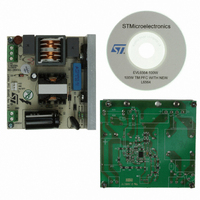
... The L6564 is a current-mode PFC controller operating in transition mode (TM). Available in an innovative and small package, the SSOP-10, the L6564 offers improved performance and protection with respect to equivalent 8-pin TM controllers. Figure 1. EVL6564-100W: L6564 100W TM PFC demonstration board November 2009 Application note Doc ID 16106 Rev 1 ...
Page 2
Contents Contents 1 Main characteristics and circuit description . . . . . . . . . . . . . . . . . . . . . 4 1.1 Electrical diagram . . . . . . . ...
Page 3
... EVL6564-100W startup with slow input voltage increasing – full load . . . . . . . . . . . . . . . . 20 Figure 26. EVL6564-100W turn-off with slow input voltage decreasing – full load . . . . . . . . . . . . . . . 20 Figure 27. EVL6564-100W startup at 90 Vac -60 Hz – full load . . . . . . . . . . . . . . . . . . . . . . . . . . . . . 20 Figure 28. EVL6564-100W startup at 265 Vac-50 Hz – full load . . . . . . . . . . . . . . . . . . . . . . . . . . . . . 20 Figure 29. EVL6564-100W load transient at 115 Vac - full load to no load Figure 30 ...
Page 4
Main characteristics and circuit description 1 Main characteristics and circuit description The main characteristics of the SMPS are: ● Line voltage range 265 Vac ● Minimum line frequency (f ● Regulated output voltage: 400 V ● Rated output ...
Page 5
AN3022 DC level equal to the peak voltage on pin #3 (MULT), is fed to a second input to the multiplier for the 1/V on the mains voltage. Additionally, the pin #5 (V providing brownout (AC mains undervoltage) protection. A ...
Page 6
... Main characteristics and circuit description 1.1 Electrical diagram Figure 2. EVL6564-100W TM PFC demonstration board: electrical schematic 6/33 Doc ID 16106 Rev 1 AN3022 ...
Page 7
... Bill of material Table 1. EVL6564-100W TM PFC bill of material Des. Part type/part value C1 470N C4 470N C5 470N - 400V C6 47µF - 450V C7 4N7 C8 680N C9 68N C10 100N C11 47uF-50V C12 2N2 C13 1uF C15 220p C16 2N2 D1 GBU4J D2 1N4005 D3 STTH2L06 D4 LL4148 D5 BZX79-C18 F1 FUSE 4A HS1 HEAT-SINK ...
Page 8
... Table 1. EVL6564-100W TM PFC bill of material (continued) Des. Part type/part value Case/package J2 MKDS 1,5/ 2-5,08 DWG J3 CON3 DWG L1 HF2826-203Y1R5-T01 DWG L2 SRW2620PQ-X22V102 DWG Q1 STF7NM50N TO-220FP R1 NTC 2R5-S237 DWG R2 1M0 1206 R8 1M0 1206 R10 1M0 1206 R3 3M3 1206 R6 3M3 1206 R4 100R 1206 R5 68K 1206 ...
Page 9
... Table 1. EVL6564-100W TM PFC bill of material (continued) Des. Part type/part value Case/package R22 100K 0805 R24 220R PTH R25 0R47 PTH R26 0R68 PTH R30 1K 0805 R31 10R 0805 R32 1M0 0805 U1 L6564D SSOP-10 Description SMD standard film res - 1/ 250ppm/°C SFR25 AXIAL STAND. FILM RES - 0. 250ppm/°C SFR25 AXIAL STAND. FILM RES - 0. 250ppm/° ...
Page 10
... Figure 3. EVL6564-100W TM PFC: compliance to EN61000-3-2 standard Vin = 230 Vac - 50 Hz, Pout = 100 W THD = 3.89 0.983 10/33 Figure 3 Figure 4. EVL6564-100W TM PFC: compliance to JEITA-MITI standard Vin = 100 Vac - 50 Hz, Pout = 100 W THD = 3.21 0.999 Doc ID 16106 Rev 1 AN3022 and Figure 4). Please note that ...
Page 11
... CH3: V bridge Figure 7 and Figure 8. As visible, the PF remains close to unity Figure 8. 9). At full load it is always higher than 94%, making this design Doc ID 16106 Rev 1 and Figure 6. EVL6564-100W TM PFC: input current waveform at 100 100 W load EVL6564-100W TM PFC: THD vs. output power Figure 10. 11/33 ...
Page 12
... Test results and significant waveforms Figure 9. EVL6564-100W TM PFC: efficiency vs. output power Figure 11. EVL6564-100W TM PFC: static Vout regulation vs. output power The measured output voltage at different line and static load conditions is given in As visible, the voltage is very stable over the entire input voltage and output load range. ...
Page 13
... CH4: L2 inductor current 17 show the waveforms relevant to the inductor current at different Figure 12 and Figure 14 Figure 13. EVL6564-100W TM PFC: Vds & CH1: Q1 drain voltage CH2: MULT voltage - Pin #3 CH4: L2 inductor current Doc ID 16106 Rev 1 Test results and significant waveforms the peak inductor current waveform ...
Page 14
... At the end of the current conduction a new demagnetization is detected by the ZCD pin that provides for a new on-time of the MOSFET. 14/33 Figure 15 the detail of the waveforms at the switching frequency allows Figure 15. EVL6564-100W TM PFC: Vds & CH1: Q1 drain voltage CH2: MULT voltage - Pin #3 CH4: L2 inductor current Figure 17 ...
Page 15
... RMS line voltage implies a form of integration, which has its own time constant too small, the voltage generated is affected by a considerable amount of Test results and significant waveforms Figure 17. EVL6564-100W TM PFC: Vds & inductor current at 230 Vac - full load CH1 Pin #9 ...
Page 16
... CH2: MULT (pin #3) CH4: I_AC Figure 19 shows the behavior of the EVL6564-100W demonstration board in case of an input voltage surge from 90 to 140Vac. In the diagram it is evident that the V provides for the stability of the output voltage which is not affected by the input voltage surge. In fact, thanks to the V very fast and the output voltage remains stable at its nominal value ...
Page 17
... V). Figure 20. L6562A input mains dip 140 Vac to 90 Vac – CH1: Vout CH2: MULT (pin #3) CH4: I_AC function. FF Figure 21. EVL6564-100W TM PFC: Input input CH1: Vout CH3 Doc ID 16106 Rev 1 Test results and significant waveforms Figure 20 shows the behavior of a PFC ...
Page 18
... L6564. Sensing of the input mains condition is done by an internal comparator connected to pin V 18/33 and Figure 23 we can see that the input current of rd harmonic current distortion is not noticeable. This demonstrates Figure 23. EVL6564-100W TM PFC: input = 390 kΩ FF THD: 3.17 CH2: MULT (pin #3) CH3 CH4: I_AC (pin #5) which delivers a voltage signal proportional to the input mains ...
Page 19
... AN3022 Figure 24. EVL6564-100W startup attempt at 80 Vac - 60 Hz – full load CH1: PFC output voltage CH2: Vcc voltage (Pin #10) CH3: V (pin #5) FF CH4: gate drive (Pin #9) Because in the L6564 the brownout thresholds are set internally, the startup and shutdown thresholds can be adjusted slightly by modifying the resistor values used for the MULT pin. ...
Page 20
... Vac -60 Hz – full load CH1: PFC output voltage CH2: Vcc voltage (Pin #10) CH3: VFF (pin #5) CH4: Gate Drive (Pin #9) 20/33 Figure 26. EVL6564-100W turn-off with slow input voltage decreasing – full load CH1: PFC output voltage CH2: gate drive (Pin #13) CH3: V (pin #5) ...
Page 21
... R15 (low), see 2 the output voltage exceeds a preset value (Vovp), usually larger than the maximum Vout that can be expected, also including worst-case load/line transients. For the EVL6564-100W we have 400 V, Vovp = 434 V. Select: R3+R4+R11=8.8MW; then: R15 = 8.8 MΩ · 2.5 / (434-2. kΩ. ...
Page 22
... Test results and significant waveforms Figure 29. EVL6564-100W load transient at 115 Vac - full load to no load CH1: PFC output voltage CH2: PFC_OK (Pin #7) CH3: GD (pin #9) CH4: Iout The event of an open loop is captured in latching the operation of the L6564. 22/33 Figure 30. EVL6564-100W open loop ...
Page 23
... DC stage starts first, it powers both controllers and enables/disables the operation of the PFC stage. The EVL6564-100W offers the possibility to test the disable function by connecting it to the cascaded DC-DC converter using the J3 connector. The PFC_OK pin, Vcc and ground are available via the series resistors R30 and R31. ...
Page 24
Power management and housekeeping functions Figure 31. Interface circuits that let DC-DC converter’s controller IC disable the L6564 24/33 Doc ID 16106 Rev 1 AN3022 ...
Page 25
AN3022 4.1 Layout hints The layout of any converter is a very important phase in the design process needing attention by the design engineers like any other design phase. Even if it the layout phase sometimes looks time-consuming, a good ...
Page 26
... Power management and housekeeping functions Figure 32. EVL6564-100W PCB layout (SMT side view) 26/33 Doc ID 16106 Rev 1 AN3022 ...
Page 27
... Figure 33. EVL6564-100W conducted emission peak measurement at 100Vac - 50Hz FL phase EMI filtering and conducted EMI pre-compliance measurements Figure 34. EVL6564-100W conducted emission peak measurement at 100Vac - 50Hz FL neutral Doc ID 16106 Rev 1 27/33 ...
Page 28
... Please note that the harmonic measurements done in quasi-peak or average as required by the regulation will be much lower because of the jittering effect of the TM control that cannot be perceived in peak detection. 28/33 Figure 36. EVL6564-100W conducted emission peak measurement at 230Vac - 50Hz FL neutral Doc ID 16106 Rev 1 ...
Page 29
AN3022 6 PFC coil specifications 6.1 General description and characteristics ● Applications: consumer, home appliance ● Transformer: open ● Coil former: vertical, 6+6 pins ● Max. temp. rise: 45 °C ● Max. operating ambient temp.: 60 °C ● Mains insulation: ...
Page 30
PFC coil specifications 6.4 Winding characteristics Table 2. Winding characteristics Pins Winding Primary AUX 1. Primary winding external insulation: 2 layers of polyester tape 2. Aux. winding is wound on top of primary winding. ...
Page 31
AN3022 7 References ● “10-pin transition-mode PFC controller” L6564 datasheet ● “How to design a TM PFC pre-regulator with the L6564” application note AN3009 Doc ID 16106 Rev 1 References 31/33 ...
Page 32
Revision history 8 Revision history Table 3. Document revision history Date 18-Nov-2009 32/33 Revision 1 Initial release Doc ID 16106 Rev 1 AN3022 Changes ...
Page 33
... AN3022 Information in this document is provided solely in connection with ST products. STMicroelectronics NV and its subsidiaries (“ST”) reserve the right to make changes, corrections, modifications or improvements, to this document, and the products and services described herein at any time, without notice. All ST products are sold pursuant to ST’s terms and conditions of sale. ...