EVLVIP17-5WCHG STMicroelectronics, EVLVIP17-5WCHG Datasheet - Page 22
EVLVIP17-5WCHG
Manufacturer Part Number
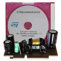
EVLVIP17-5WCHG
Description
BOARD EVAL FOR VIPER17
Manufacturer
STMicroelectronics
Series
VIPer™ plusr
Specifications of EVLVIP17-5WCHG
Main Purpose
AC/DC, Primary and Secondary Side
Outputs And Type
1, Isolated
Power - Output
5W
Voltage - Output
5.1V
Current - Output
1A
Voltage - Input
90 ~ 264VAC
Regulator Topology
Flyback
Frequency - Switching
115kHz
Board Type
Fully Populated
Utilized Ic / Part
TSM1052, VIPer17
Lead Free Status / RoHS Status
Lead free / RoHS Compliant
Other names
497-8250
Available stocks
Company
Part Number
Manufacturer
Quantity
Price


Operation descriptions
22/31
Equation 7
Equation 8
The R
The C
The
considered instead of C
satisfy, in all case, the loop stability and the enough OLP delay time alike.
Figure 28. FB pin configuration
Figure 29. FB pin configuration
Equation 5
FB(DYN)
FB1
capacitor fixes the OLP delay and usually C
is the dynamic resistance seen by the FB pin.
can be still used to calculate the OLP delay time but C
Rfb1
Cfb1
FB
. Using the alternative compensation network, the designer can
Cfb
f
f
PFB
PFB
Cfb
Doc ID 14419 Rev 7
1
=
=
2
2
⋅
⋅
⋅ π
⋅ π
CONTROL
R
C
C
PWM
FB
FB
FB
CONTROL
PWM
BURST-MODE
1
(
DYN
References
⋅
⋅
(
(
R
R
1
FB
)
FB
References
+
V FBolp
1
(
DYN
R
+
V FBolp
FB
R
FB1
)
FB
OLP comparator
1
⋅
R
(
DYN
results much higher than C
BURST-MODE
PWM
OLP comparator
FB
From sense FET
+
+
-
-
LOGIC
1
)
BURST-MODE
)
)
PWM
From R
+
+
-
-
LOGIC
SENSE
To disable logic
To PWM Logic
To disable logic
FB1
BURST
To GATE driver
BURST
has to be
VIPER17
FB
.
Related parts for EVLVIP17-5WCHG
Image
Part Number
Description
Manufacturer
Datasheet
Request
R

Part Number:
Description:
STMicroelectronics [RIPPLE-CARRY BINARY COUNTER/DIVIDERS]
Manufacturer:
STMicroelectronics
Datasheet:
Part Number:
Description:
STMicroelectronics [LIQUID-CRYSTAL DISPLAY DRIVERS]
Manufacturer:
STMicroelectronics
Datasheet:

Part Number:
Description:
BOARD EVAL FOR MEMS SENSORS
Manufacturer:
STMicroelectronics
Datasheet:
Part Number:
Description:
NPN TRANSISTOR POWER MODULE
Manufacturer:
STMicroelectronics
Datasheet:
Part Number:
Description:
TURBOSWITCH ULTRA-FAST HIGH VOLTAGE DIODE
Manufacturer:
STMicroelectronics
Datasheet:
Part Number:
Description:
Manufacturer:
STMicroelectronics
Datasheet:
Part Number:
Description:
DIODE / SCR MODULE
Manufacturer:
STMicroelectronics
Datasheet:
Part Number:
Description:
DIODE / SCR MODULE
Manufacturer:
STMicroelectronics
Datasheet:
Part Number:
Description:
Search -----> STE16N100
Manufacturer:
STMicroelectronics
Datasheet:
Part Number:
Description:
Search ---> STE53NA50
Manufacturer:
STMicroelectronics
Datasheet:
Part Number:
Description:
NPN Transistor Power Module
Manufacturer:
STMicroelectronics
Datasheet:
Part Number:
Description:
DIODE / SCR MODULE
Manufacturer:
STMicroelectronics
Datasheet: