STEVAL-ISA028V1 STMicroelectronics, STEVAL-ISA028V1 Datasheet - Page 10
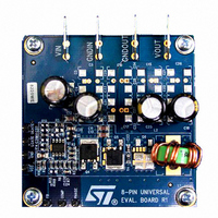
STEVAL-ISA028V1
Manufacturer Part Number
STEVAL-ISA028V1
Description
BOARD EVAL 1PH STPDWN CONV L6727
Manufacturer
STMicroelectronics
Type
DC/DC Switching Converters, Regulators & Controllersr
Specifications of STEVAL-ISA028V1
Design Resources
STEVAL-ISA028V1 Gerber Files STEVAL-ISA028V1 Schematic STEVAL-ISA028V1 Bill of Materials
Main Purpose
DC/DC, Step Down
Outputs And Type
1, Non-Isolated
Voltage - Output
1.25V
Current - Output
20A
Voltage - Input
5 ~ 12V
Regulator Topology
Buck
Frequency - Switching
300kHz
Board Type
Fully Populated
Utilized Ic / Part
L6727
Input Voltage
5 V to 12 V
Output Voltage
1.25 V
Product
Power Management Modules
Lead Free Status / RoHS Status
Lead free / RoHS Compliant
Power - Output
-
Lead Free Status / Rohs Status
Lead free / RoHS Compliant
For Use With/related Products
L6727
Other names
497-6258
Available stocks
Company
Part Number
Manufacturer
Quantity
Price
Company:

Part Number:
STEVAL-ISA028V1
Manufacturer:
STMicroelectronics
Quantity:
135
Company:
Part Number:
STEVAL-ISA028V1
Manufacturer:
STMicroelectronics
Quantity:
1


Driver section
5
5.1
10/34
Driver section
The integrated high-current drivers allow using different types of power MOSFET (also
multiple MOSFETs to reduce the equivalent R
The driver for the high-side MOSFET uses BOOT pin for supply and PHASE pin for return.
The driver for low-side MOSFET uses the VCC pin for supply and GND pin for return.
The controller embodies an anti-shoot-through and adaptive dead-time control to minimize
low side body diode conduction time, maintaining good efficiency while saving the use of
Schottky diode:
●
●
If the current flowing in the inductor is negative, voltage on PHASE pin will never drop. To
allow the low-side MOSFET to turn-on even in this case, a watchdog controller is enabled: if
the source of the high-side MOSFET doesn't drop, the low side MOSFET is switched on so
allowing the negative current of the inductor to recirculate. This mechanism allows the
system to regulate even if the current is negative.
Power conversion input is flexible: 5 V, 12 V bus or any bus that allows the conversion (See
maximum duty cycle limitation and recommended operating conditions, in
chosen freely.
Power dissipation
L6727 embeds high current MOSFET drivers for both high side and low side MOSFETs: it is
then important to consider the power that the device is going to dissipate in driving them in
order to avoid overcoming the maximum junction operative temperature.
Two main terms contribute in the device power dissipation: bias power and drivers' power.
●
●
to check high-side MOSFET turn off, PHASE pin is sensed. When the voltage at
PHASE pin drops down, the low-side MOSFET gate drive is suddenly applied;
to check low-side MOSFET turn off, LGATE pin is sensed. When the voltage at LGATE
has fallen, the high-side MOSFET gate drive is suddenly applied.
Device bias power (P
supply pins and it is simply quantifiable as follow (assuming to supply HS and LS
drivers with the same VCC of the device):
Drivers power is the power needed by the driver to continuously switch on and off the
external MOSFETs; it is a function of the switching frequency and total gate charge of
the selected MOSFETs. It can be quantified considering that the total power P
dissipated to switch the MOSFETs (easy calculable) is dissipated by three main
factors: external gate resistance (when present), intrinsic MOSFET resistance and
intrinsic driver resistance. This last term is the important one to be determined to
calculate the device power dissipation. The total power dissipated to switch the
MOSFETs results:
where V
resistors helps the device to dissipate the switching power since the same power P
will be shared between the internal driver impedance and the external resistor resulting
in a general cooling of the device.
BOOT
P
SW
- V
=
PHASE
F
SW
DC
is the voltage across the bootstrap capacitor. External gate
) depends on the static consumption of the device through the
P
⋅
Doc ID 12933 Rev 4
[
DC
Q
gHS
=
V
⋅
(
CC
V
BOOT
⋅
(
dsON
I
CC
–
), maintaining fast switching transition.
+
V
I
PHASE
BOOT
)
)
+
Q
gLS
⋅
V
Table
CC
]
5) can be
SW
L6727
SW
Related parts for STEVAL-ISA028V1
Image
Part Number
Description
Manufacturer
Datasheet
Request
R

Part Number:
Description:
BOARD RGB CTR ST7,STP08C596MTR
Manufacturer:
STMicroelectronics
Datasheet:

Part Number:
Description:
Power Management IC Development Tools Full Speed USB to RS232 Bridge Demo
Manufacturer:
STMicroelectronics
Datasheet:
Part Number:
Description:
Power Management IC Development Tools 2.5W solar eval BRD USB SPV1040 LD39050
Manufacturer:
STMicroelectronics
Datasheet:

Part Number:
Description:
BOARD EVAL FOR MEMS SENSORS
Manufacturer:
STMicroelectronics
Datasheet:

Part Number:
Description:
KIT DEV STARTER ST10F276Z5
Manufacturer:
STMicroelectronics
Datasheet:

Part Number:
Description:
BOARD EVAL HDMI $ VIDEO SWITCH
Manufacturer:
STMicroelectronics
Datasheet:

Part Number:
Description:
BOARD DEMO ACCELEROMETER DIL24
Manufacturer:
STMicroelectronics
Datasheet:

Part Number:
Description:
BOARD STLM75/STDS75/ST72F651
Manufacturer:
STMicroelectronics
Datasheet:

Part Number:
Description:
EVAL BOARD 3AXIS MEMS ACCELLRMTR
Manufacturer:
STMicroelectronics
Datasheet:

Part Number:
Description:
BOARD EVAL 8BIT MICRO + TDE1708
Manufacturer:
STMicroelectronics
Datasheet:
Part Number:
Description:
STMicroelectronics [RIPPLE-CARRY BINARY COUNTER/DIVIDERS]
Manufacturer:
STMicroelectronics
Datasheet:
Part Number:
Description:
STMicroelectronics [LIQUID-CRYSTAL DISPLAY DRIVERS]
Manufacturer:
STMicroelectronics
Datasheet:
Part Number:
Description:
BOARD EVAL FOR MEMS SENSORS
Manufacturer:
STMicroelectronics
Datasheet: