DAK-85 Power Integrations, DAK-85 Datasheet - Page 8
DAK-85
Manufacturer Part Number
DAK-85
Description
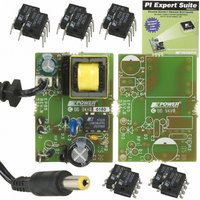
DESIGN ACCELERATOR KIT LP SWITCH
Manufacturer
Power Integrations
Series
LinkSwitch®-LPr
Specifications of DAK-85
Main Purpose
AC/DC, Primary Side
Outputs And Type
1, Isolated
Power - Output
2W
Voltage - Output
6V
Current - Output
330mA
Voltage - Input
90 ~ 265VAC
Regulator Topology
Flyback
Frequency - Switching
66kHz
Board Type
Bare (Unpopulated) and Fully Populated
Utilized Ic / Part
LNK562, LNK563, LNK564
Lead Free Status / RoHS Status
Lead free / RoHS Compliant
Other names
596-1104
Available stocks
Company
Part Number
Manufacturer
Quantity
Price
Company:

Part Number:
DAK-85
Manufacturer:
Power Integrations
Quantity:
135


No-load consumption can be further reduced by increasing C3 to 0.47 µF or higher.
4.3 Primary Clamp and Transformer Construction
A Clampless primary circuit is achieved due to the very tight tolerance current limit
trimming techniques used in manufacturing the LNK564, plus the transformer
construction techniques used. Peak drain voltage is therefore limited to typically less than
550 V at 265 VAC – providing significant margin to the 700 V minimum drain voltage
specification (BV
4.4 Output Rectification and Filtering
Output rectification and filtering is achieved with output rectifier D4 and filter capacitor C5.
Due to the auto-restart feature, the average short circuit output current is significantly less
than 1 A, allowing low cost rectifier D4 to be used. Output circuitry is designed to handle
a continuous short circuit on the power supply output. Diode D4 is an ultra-fast type,
selected for optimum V/I output characteristics. Optional resistor R3 provides a pre-load,
limiting the output voltage level under no-load output conditions. Despite this pre-load,
no-load consumption is within targets at approximately 140 mW at 265 VAC. The
additional margin of no-load consumption requirement can be achieved by increasing the
value of R4 to 2.2 kΩ or higher while still maintaining output voltage well below the 9 V
maximum specification. Placement is left on the board for an optional Zener clamp (VR1)
to limit maximum output voltage under open loop conditions, if required.
4.5 Optional Components
Fusible resistor RF1, VR1 and C4 are all optional components. Resistor RF1, VR1 and
C4 are not fitted on the board as standard, RF1 being replaced with a wire link.
• Resistor RF1 may be fitted to designs where a traditional fuse is preferred over the
• Zener diode VR1 is fitted where the output voltage must be limited to a lower value
• The use of E-Shield
Filterfuse configuration.
during open loop conditions. The auto-restart feature of LinkSwitch-LP limits the
output power under this condition, requiring only a zener with a low, 0.5 W rating.
safety capacitor across the safety isolation barrier to meet EMI. However, the use
of C4, a small value (100 pF) Y1 capacitor provides improved EMI consistency if
transformer construction variation is a concern.
Power Integrations
Tel: +1 408 414 9200 Fax: +1 408 414 9201
www.powerint.com
DSS
).
TM
techniques in the transformer removes the need for a Y1
Page 8 of 32
Related parts for DAK-85
Image
Part Number
Description
Manufacturer
Datasheet
Request
R

Part Number:
Description:
KIT DESIGN ACCELERATOR MODEM
Manufacturer:
Power Integrations
Datasheet:

Part Number:
Description:
KIT DESIGN ACCELERATOR SET TOP
Manufacturer:
Power Integrations
Datasheet:

Part Number:
Description:
KIT REF DES DPA 6.6W DC-DC CONV
Manufacturer:
Power Integrations
Datasheet:

Part Number:
Description:
KIT DESIGN ACCELERATOR POE CONV
Manufacturer:
Power Integrations
Datasheet:

Part Number:
Description:
DESIGN ACCELERATOR KIT XT SWITCH
Manufacturer:
Power Integrations
Datasheet:

Part Number:
Description:
KIT DESIGN ACC PEAKSWITCH FAMILY
Manufacturer:
Power Integrations
Datasheet:

Part Number:
Description:
KIT DESIGN ACCELERATOR ADAPTER
Manufacturer:
Power Integrations
Datasheet:

Part Number:
Description:
KIT DESIGN ACCELERATOR ADAPTER
Manufacturer:
Power Integrations
Datasheet:

Part Number:
Description:
KIT DESIGN ACCELERATOR DC-DC
Manufacturer:
Power Integrations
Datasheet:

Part Number:
Description:
KIT DESIGN ACCELERATOR DPA SW
Manufacturer:
Power Integrations
Datasheet: