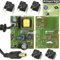
DAK-85 Power Integrations, DAK-85 Datasheet
DAK-85
Specifications of DAK-85
Available stocks


Related parts for DAK-85


DAK-85 Summary of contents
Page 1
... Engineering Prototype Report for EP-85 – Charger using LinkSwitch Title (LNK564P) 90 – 265 VAC Input 330 mA Output Specification Low Cost, Line Frequency Transformer Based Application Charger Replacement Power Integrations Strategic Marketing Department Author Document EPR-85 Number 04-Oct-2005 Date 1.0 Revision Summary and Features • ...
Page 2
... The products and applications illustrated herein (including circuits external to the products and transformer construction) may be covered by one or more U.S. and foreign patents or potentially by pending U.S. and foreign patent applications assigned to Power Integrations. A complete list of Power Integrations’ patents may be found at www.powerint.com. Power Integrations Tel: +1 408 414 9200 Fax: +1 408 414 9201 www ...
Page 3
... Although this board is designed to satisfy safety isolation requirements, the engineering prototype has not been agency approved. Therefore, all testing should be performed using an isolation transformer to provide the AC input to the prototype board. Page Power Integrations Tel: +1 408 414 9200 Fax: +1 408 414 9201 www.powerint.com ...
Page 4
... European standards and even 150 mW at 230 VAC targets set in some customer specifications. Heat generation is minimized with high operating efficiency under all load and line conditions. The EE16 transformer bobbin provides extended creepage to meet safety spacing requirements. Power Integrations Tel: +1 408 414 9200 Fax: +1 408 414 9201 www.powerint.com Page ...
Page 5
... Figure 1 – LNK564 Low Cost Cell Phone Charger Populated Circuit Board Photograph. Page Power Integrations Tel: +1 408 414 9200 Fax: +1 408 414 9201 www.powerint.com ...
Page 6
... Continuous Output Power Efficiency Environmental Conducted EMI Safety Surge External Ambient Temperature 0.1 0.2 Figure 2 – Low Cost Charger Output Envelope Specification. Power Integrations Tel: +1 408 414 9200 Fax: +1 408 414 9201 www.powerint.com Symbol Min Typ Max 90 265 LINE 0.15 5 OUT1 200 V ...
Page 7
... FB pin voltage reaches the auto-restart threshold voltage (typically 0 the FB pin, which is equivalent 1 the output of the power supply). This function limits the output current in this region without fold back until the output voltage is low. Page Power Integrations Tel: +1 408 414 9200 Fax: +1 408 414 9201 www.powerint.com ...
Page 8
... The use of E-Shield safety capacitor across the safety isolation barrier to meet EMI. However, the use of C4, a small value (100 pF) Y1 capacitor provides improved EMI consistency if transformer construction variation is a concern. Power Integrations Tel: +1 408 414 9200 Fax: +1 408 414 9201 www.powerint.com TM ...
Page 9
... PCB Layout Figure 4 – LNK564 Low Cost Charger Printed Circuit Layout. Page Power Integrations Tel: +1 408 414 9200 Fax: +1 408 414 9201 www.powerint.com ...
Page 10
... Vishay 1N4005 Vishay UF4002 Keystone 5011 Generic Epcos B78108S1335J Generic Yageo MFR-25FBF-37K4 Yageo CFR-12JB-3K0 Yageo CFR-12JB-2K0 Vitrohm CRF253-4 5T 8R2 Ngai Cheong EE-16 10PINs Electronics Falco E09077 Hical SIL6036 CWS CWS-T1-DAK85 Li Shin LSLA40342 Woo Jin SLP-2218P1 Power LNK564P Integrations Microsemi 1N5240B Page ...
Page 11
... From pins 1-2, all other windings open All windings open From pins 1-2 with pins 6-7 shorted Tel: +1 408 414 9200 Fax: +1 408 414 9201 7 Secondary WDG #4 0.5 mm T.I. Cut WDG #3 Shield 0.25 mm × 3000 VAC 2.7 mH, -/+ (Max.) 75 µH (Max.) Power Integrations www.powerint.com ...
Page 12
... Primary 0. Bias 4 0 Barrier tape See Fig. 7 for detail of shield winding start technique. Power Integrations Tel: +1 408 414 9200 Fax: +1 408 414 9201 www.powerint.com Description 2 230 nH/T LG Figure 6 – Transformer Build Diagram. Iso. Tape 7 6 Iso. Tape Iso. Tape Iso ...
Page 13
... Start winding here from edge of margin tape. Plastic tape Position three wires to line up with outside edge of margin tape and stick wires down with plastic tape. No empty space among the wires. Power Integrations Tel: +1 408 414 9200 Fax: +1 408 414 9201 www.powerint.com ...
Page 14
... KP ENTER TRANSFORMER CORE/CONSTRUCTION VARIABLES Core Type Core Bobbin Power Integrations Tel: +1 408 414 9200 Fax: +1 408 414 9201 www.powerint.com INFO OUTP UNIT ACDC_LinkSwitch-LP_091605_Rev1-0.xls; LinkSwitch-LP UT Continuous/Discontinuous Flyback Transformer Design Spreadsheet EP85 Design Volts Minimum AC Input Voltage Volts Maximum AC Input Voltage Hertz AC Mains Frequency ...
Page 15
... Peak Drain Voltage is highly dependent on Transformer capacitance and leakage inductance. Please verify this on the bench and ensure that it is below 650 V to allow 50 V margin for transformer variation. 34 Volts Output Rectifier Maximum Peak Inverse Voltage Tel: +1 408 414 9200 Fax: +1 408 414 9201 Power Integrations www.powerint.com ...
Page 16
... The CEC & EPA spec shown in the table below was calculated based the nominal 100% load. 25% Input Voltage Relative P OUT 115 VAC 65.0 230 VAC 60.5 Power Integrations Tel: +1 408 414 9200 Fax: +1 408 414 9201 www.powerint.com 1.00 1.50 Output Power (W) – Efficiency vs. Output Power. Figure 8 50% 75% ...
Page 17
... AC Input Voltage (VAC) 0.3 0.4 0.5 0.6 0.7 Output Current (A) Figure 10 – Load and Line Regulation. Tel: +1 408 414 9200 Fax: +1 408 414 9201 250 300 at 90 VAC at 115 VAC at 230 VAC at 265 VAC MIN MAX 0.8 0.9 1 1.1 1.2 Power Integrations www.powerint.com ...
Page 18
... An infrared thermograph was taken of the unit operating open frame at room ambient. This confirms that the correct components were selected for temperature measurement in the table above and that high line is worst case for U1. Power Integrations Tel: +1 408 414 9200 Fax: +1 408 414 9201 www.powerint.com Measured Temperature Rise (° ...
Page 19
... VAC load, 22°C Ambient 90 VAC load, 22°C Ambient Figure 11 – Infra-Red Thermograph of Unit Operating Open Frame, Room Ambient Page Power Integrations Tel: +1 408 414 9200 Fax: +1 408 414 9201 www.powerint.com ...
Page 20
... Drain Voltage and Current, Normal Operation Figure 12 – 90 VAC, Full Load. Upper 0. div. DRAIN Lower 200 V, 2 µs / div. DRAIN Power Integrations Tel: +1 408 414 9200 Fax: +1 408 414 9201 www.powerint.com Figure 13 – 265 VAC, Full Load. Upper 0. div. DRAIN Lower 200 V / div, 2 µ ...
Page 21
... I Page Ω. LOAD Figure 16 – Battery Start-Up Profile, 265 VAC. Upper: I Lower: V DRAIN at the end of the switching cycle. DRAIN Tel: +1 408 414 9200 Fax: +1 408 414 9201 , 0. div. DRAIN , div. OUT waveform in Figure 15 is Power Integrations www.powerint.com ...
Page 22
... At start-up with a battery load, Drain current and Drain voltages are well controlled and within acceptable operating limits. Note that the peak of the I is the leading edge current spike not I Power Integrations Tel: +1 408 414 9200 Fax: +1 408 414 9201 www.powerint.com Figure 18 – 265 VAC Input and Maximum Load. ...
Page 23
... DC output cable assembly. Figure 19 – Oscilloscope Probe with Probe Master 5125BA BNC Adapter (modified with wires for probe ground for ripple measurement, and two parallel decoupling capacitors added). Page Power Integrations Tel: +1 408 414 9200 Fax: +1 408 414 9201 www.powerint.com ...
Page 24
... & 20 µs, 100 mV / div. Under worst-case 90 VAC and 265 VAC and maximum loading conditions, total switching output ripple is below 150 mV pk-pk. Power Integrations Tel: +1 408 414 9200 Fax: +1 408 414 9201 www.powerint.com Figure 21 – V Ripple, 90 VAC / 60 Hz & 20 µs, 100 mV / div. ...
Page 25
... Att 10 dB AUTO PREAMP OFF 1 MHz 10 MHz LIMIT CHECK PASS RBW 9 kHz MT 500 ms Att 10 dB AUTO PREAMP OFF 1 MHz 10 MHz LIMIT CHECK PASS Tel: +1 408 414 9200 Fax: +1 408 414 9201 SGL TDF 30 MHz SGL TDF 30 MHz Power Integrations www.powerint.com ...
Page 26
... Figure 26 – Conducted Emissions, Line 230 VAC, 17 Ω Load, with Artificial Hand at Output. QP-Dark Blue, AVG-Red The EMI results show >9 dB margin worst case to quasi-peak and average EN55022B limits. Power Integrations Tel: +1 408 414 9200 Fax: +1 408 414 9201 www.powerint.com RBW ...
Page 27
... Unit passes under all test conditions. Page Input Injection Phase Voltage Location Injection (°) (VAC) 230 230 230 230 230 230 230 230 Tel: +1 408 414 9200 Fax: +1 408 414 9201 Test Result (Pass/Fail) Pass Pass Pass Pass Pass Pass Pass Pass Power Integrations www.powerint.com ...
Page 28
... Revision History Date Author 04-Oct-05 SM/SR Power Integrations Tel: +1 408 414 9200 Fax: +1 408 414 9201 www.powerint.com Revision Description & changes 1.0 Formatted for Final Release Page ...
Page 29
... Page Notes Power Integrations Tel: +1 408 414 9200 Fax: +1 408 414 9201 www.powerint.com ...
Page 30
... Power Integrations Tel: +1 408 414 9200 Fax: +1 408 414 9201 www.powerint.com Notes Page ...
Page 31
... Page Notes Power Integrations Tel: +1 408 414 9200 Fax: +1 408 414 9201 www.powerint.com ...
Page 32
... For the latest updates, visit our website: www.powerint.com Power Integrations reserves the right to make changes to its products at any time to improve reliability or manufacturability. Power Integrations does not assume any liability arising from the use of any device or circuit described herein. POWER INTEGRATIONS MAKES NO WARRANTY HEREIN AND SPECIFICALLY DISCLAIMS ALL WARRANTIES INCLUDING, WITHOUT LIMITATION, THE IMPLIED WARRANTIES OF MERCHANTABILITY, FITNESS FOR A PARTICULAR PURPOSE, AND NON-INFRINGEMENT OF THIRD PARTY RIGHTS ...