DM300023 Microchip Technology, DM300023 Datasheet - Page 43
DM300023
Manufacturer Part Number
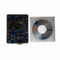
DM300023
Description
KIT DEMO DSPICDEM SMPS BUCK
Manufacturer
Microchip Technology
Series
dsPIC™r
Datasheets
1.AC164335.pdf
(286 pages)
2.DM300023.pdf
(22 pages)
3.DM300023.pdf
(18 pages)
4.DM300023.pdf
(50 pages)
5.DM300023.pdf
(16 pages)
Specifications of DM300023
Main Purpose
DC/DC, Step Down
Outputs And Type
2, Non-Isolated
Voltage - Input
7 ~ 15V
Regulator Topology
Buck
Board Type
Fully Populated
Utilized Ic / Part
dsPIC30F2020
Processor To Be Evaluated
dsPIC30F202x/1010
Interface Type
RS-232
Lead Free Status / RoHS Status
Lead free / RoHS Compliant
Current - Output
-
Voltage - Output
-
Power - Output
-
Frequency - Switching
-
Lead Free Status / Rohs Status
Lead free / RoHS Compliant
Available stocks
Company
Part Number
Manufacturer
Quantity
Price
Company:

Part Number:
DM300023
Manufacturer:
Microchip Technology
Quantity:
135
Company:
Part Number:
DM300023
Manufacturer:
MICROCHIP
Quantity:
12 000


4.2
© 2006 Microchip Technology Inc.
DEMONSTRATION CODE
4.2.1
When power is applied to the board, the program starts by executing these system
initialization routines:
• Peripherals – The required peripherals (PWM, ADC, Timers, GPIO) are
• Variables – Program variables are defined. RAM locations and register usage are
• Constants – Program constants are defined, including reference setpoints for
• Interrupts – The ADC and Timer Interrupts are set up and enabled.
• Soft Start – The Soft Start flag is set
• System Stabilization – All outputs are discharged to ensure a stable value at
4.2.2
The program checks the ADC for input undervoltage and output overvoltage condi-
tions. If a fault occurs, the PWM outputs are disabled until the fault condition is cleared.
If no fault is detected, the program proceeds.
4.2.3
If the Soft Start flag is set, the Soft Start Routine ramps up the output voltage in an
open-loop fashion to bring the system within the operating range of the PID control
loop. This routine ensures that the output does not overshoot the desired voltage. It
also limits the current at startup.
4.2.4
The ADC Interrupt is the heart of the demo program. This routine takes up approxi-
mately 75% of the execution time. It performs all the PID calculations and applies any
needed corrections to the output
Two simultaneous PID loops are being processed (one for VOUT1 and the other for
VOUT2). Each loop has its own variables, constants and peripheral initialization.
Key points to note are:
• The ADC Interrupt can occur at any time during program execution, and
• It takes priority over any other tasks that the program is performing.
4.2.5
All auxiliary functions are performed in the System Idle routine. This is the time avail-
able to the CPU while the demo program is waiting for an ADC Interrupt. Non-critical
functions can be performed in this loop. During this time the input voltage, fault timers
and Soft Start flag are checked.
configured and enabled.
also defined and documented.
both VOUT1 and VOUT2, input voltage, current limits, fault conditions, PWM
periods and Timer periods.
startup.
System Initialization
Fault Check
Soft Start
ADC Interrupt
System Idle Loop
DS70181A-page 39
Related parts for DM300023
Image
Part Number
Description
Manufacturer
Datasheet
Request
R

Part Number:
Description:
Manufacturer:
Microchip Technology Inc.
Datasheet:
Part Number:
Description:
Manufacturer:
Microchip Technology Inc.
Datasheet:
Part Number:
Description:
Manufacturer:
Microchip Technology Inc.
Datasheet:
Part Number:
Description:
Manufacturer:
Microchip Technology Inc.
Datasheet:
Part Number:
Description:
Manufacturer:
Microchip Technology Inc.
Datasheet:
Part Number:
Description:
Manufacturer:
Microchip Technology Inc.
Datasheet:
Part Number:
Description:
Manufacturer:
Microchip Technology Inc.
Datasheet:
Part Number:
Description:
Manufacturer:
Microchip Technology Inc.
Datasheet: