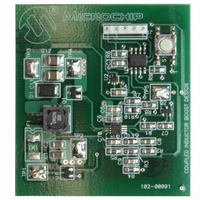
MCP1630DM-DDBS2 Microchip Technology, MCP1630DM-DDBS2 Datasheet - Page 16

MCP1630DM-DDBS2
Manufacturer Part Number
MCP1630DM-DDBS2
Description
BOARD DEMO BOOST COUPLED INDUCTR
Manufacturer
Microchip Technology
Type
DC/DC Switching Converters, Regulators & Controllersr
Specifications of MCP1630DM-DDBS2
Main Purpose
DC/DC, Step Up
Outputs And Type
1, Non-Isolated
Voltage - Output
15 ~ 40V
Current - Output
30mA
Voltage - Input
3 ~ 5.5V
Regulator Topology
Boost
Frequency - Switching
100kHz
Board Type
Fully Populated
Utilized Ic / Part
MCP1630
Output Voltage
15 V to 40 V
Product
Power Management Modules
For Use With/related Products
MCP1630, PIC12F683
Lead Free Status / RoHS Status
Not applicable / Not applicable
Power - Output
-
Lead Free Status / Rohs Status
Lead free / RoHS Compliant
MCP1630/MCP1630V
5.0
5.1
The MCP1630/V high-speed PWM can be used for any
circuit topology and power-train application when
combined with a microcontroller. Intelligent, cost-
effective power systems can be developed for applica-
tions that require multiple outputs, multiple phases,
adjustable
calibration.
5.2
A typical NiMH battery charger application is shown in
the “Typical Application Circuit – MCP1630” of this
data sheet. In that example, a Single-Ended Primary
Inductive Converter (SEPIC) is used to provide a
constant charge current to the series-connected
batteries. The MCP1630 is used to regulate the charge
current by monitoring the current through the battery
sense resistor and providing the proper pulse width.
The PIC16F818 monitors the battery voltage to provide
a termination to the charge current. Additional features
(trickle charge, fast charge, overvoltage protection,
etc.) can be added to the system using the programma-
bility of the microcontroller and the flexibility of the
MCP1630.
DS21896B-page 16
APPLICATION
CIRCUITS/ISSUES
Typical Applications
NiMH Battery Charger Application
outputs,
temperature monitoring
and
5.3
A bidirectional Li-Ion charger/buck regulator is shown
in the “Typical Application Circuit” of the this data
sheet. In this example, a synchronous, bidirectional
power converter example is shown using the
MCP1630V. In this application, when the ac-dc input
power is present, the bidirectional power converter is
used to charge 4-series Li-Ion batteries by boosting the
input voltage. When ac-dc power is removed, the
bidirectional power converter bucks the battery voltage
down to provide a dc bus for system power. By using
this method, a single power train is capable of charging
4-series cell Li-Ion batteries and efficiently converting
the battery voltage down to a low, usable voltage.
5.4
By using additional MCP1630 devices, multiple output
converters can be developed using a single MCU. If a
two-output converter is desired, the MCU can provide
two PWM outputs that are phased 180° apart. This will
reduce the input ripple current to the source and
eliminate beat frequencies.
Bidirectional Power Converter
Multiple Output Converters
© 2005 Microchip Technology Inc.


